
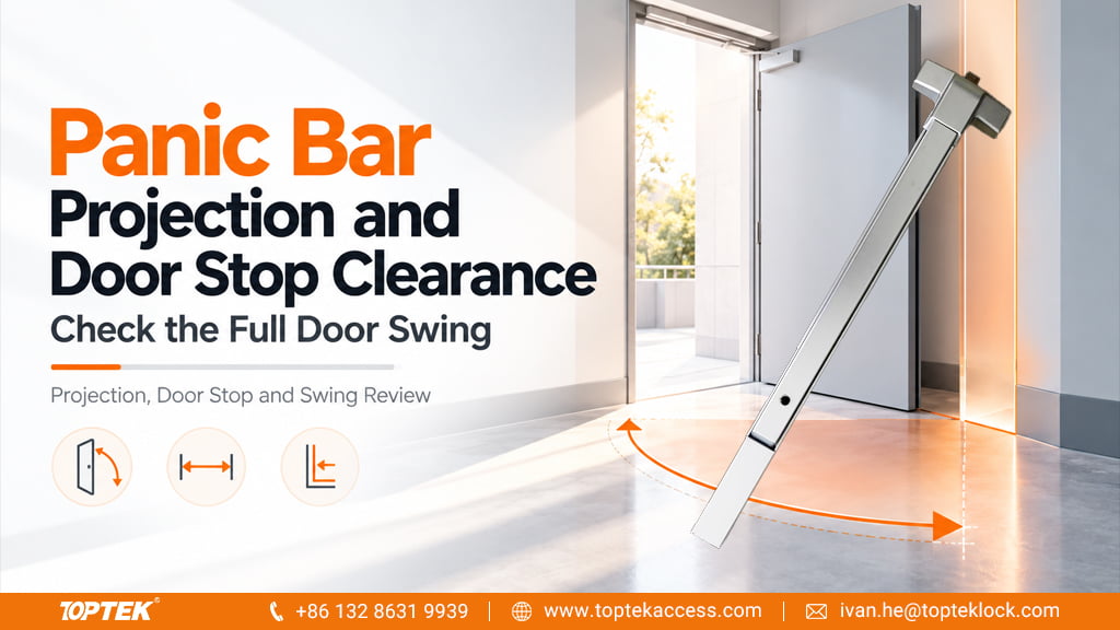

A panic bar can fit the width of a door and still collide with the wall when the leaf opens. For door manufacturers and hardware buyers, that is a coordination problem between the exit device, hinge geometry, adjacent construction and opening stop. TOPTEK’s panic exit device range provides the product starting point; the final clearance check belongs to the complete opening.
TL;DR
- Record the greatest projection of the complete device, including covers and end caps.
- Check the moving hardware through the full intended door swing, with the touch bar released and operated.
- Locate the opening stop so its intended contact surface receives the stopping load before the exit device touches an obstruction.
- Review accessible passage space separately from collision clearance, using the applicable project requirements.
Quick Answer
Panic bar projection clearance is the space needed between the installed exit device and surrounding construction as the door moves. Check it from the finished door face using the exact device drawing, then include the hinge or pivot location, wall returns, neighbouring leaves and proposed opening stop. A clear closed-door photograph does not establish safe movement. The assembled door should reach its required opening position without the bar, chassis, rods or trim contacting an obstruction. Specify the stop and its support together with the device, rather than choosing a buffer after installation.
Separate three different clearance questions
First, can the hardware physically pass the wall, frame or adjacent leaf? This is a collision question. Second, can a person operate the bar and move through the opening? This concerns operating space and accessible passage. Third, where does the door’s opening movement stop, and which component receives that load? This concerns the stopping arrangement and its fixing support.
A layout can pass one question and fail another. Moving a floor stop outward might protect the chassis but leave an obstacle in a circulation route. Restricting the opening angle might avoid a wall collision but reduce the usable opening. A deeply projecting wall buffer might contact the moving touch bar instead of a suitable door surface. The review therefore needs an opening plan and a hardware elevation, not just the catalogue’s overall bar length.
For U.S. accessible routes, the U.S. Access Board guide to doors and gates treats clear width, projections and maneuvering space as distinct requirements. Apply the relevant provisions to the actual opening and project scope. Those requirements do not supply a universal wall-buffer position or certify a particular TOPTEK device.
Build a projection and obstruction schedule
Measure projection perpendicular to the finished mounting face. Include any mounting accessories that change the installed position. Record the component that establishes the maximum envelope; the chassis may project farther than the touch bar, and a remote rod cover can introduce an obstruction at another height. A single measurement taken at the middle of the bar can miss both.
| Item | Record | Decision it supports |
|---|---|---|
| Device body and touch bar | Installed projection in released and operated positions | Clearance through the door swing |
| Chassis and end cap | Maximum envelope and location on the leaf | First potential contact with wall or neighbouring hardware |
| Rods and covers where fitted | Projection at each relevant height | Upper and lower interference checks |
| Hinge or pivot | Axis relative to door face and frame | Actual hardware travel path |
| Opening stop | Location, contact face, support and intended stopping position | Controlled stopping before unwanted contact |
| Adjacent construction | Finished wall, skirting, glazing, cabinet and adjacent leaf positions | Coordination with completed building conditions |
Ask for the drawing revision used for these entries. Request separate dimensions for the touch bar, chassis, end section and any remote covers. Record which component establishes the greatest projection at each relevant height; do not substitute a dimension from another device because the assemblies appear similar.
Check the full swing before setting the stop
On a plan drawing, plot the hinge axis and the farthest relevant points of the installed device. Follow their movement from closed to the required open position. Include the wall finish and any obstruction that is absent from the structural drawing. A projecting handle on a nearby cupboard, for example, can become the first contact even when the wall itself is clear.
Then check the proposed stop contact. The stop should act through a suitable surface and fixing arrangement for that door construction. It should not use the touch bar, end cap or rod cover as an improvised bumper. If the intended contact point falls on glazing, thin unsupported skin or another hardware item, ask the door and hardware suppliers for a coordinated alternative.
A drawing establishes the proposed geometry; a representative assembly tests the real combination. With the opening managed for testing, move the door slowly through its intended range. Observe the closest approach at several heights and repeat with the touch bar in its normal and operated positions. Record the stop contact, maximum opening position and any remaining interference. This is an observation procedure, not permission to alter a listed assembly or bypass exit operation.
Consider movement beyond the first gentle contact as well. Stop compression, fixing movement and door flexibility can change the final position under use. The project designer should define the allowance and suitable stopping hardware. Do not substitute an invented universal gap for a model-specific review.
Coordinate rods, paired leaves and service access
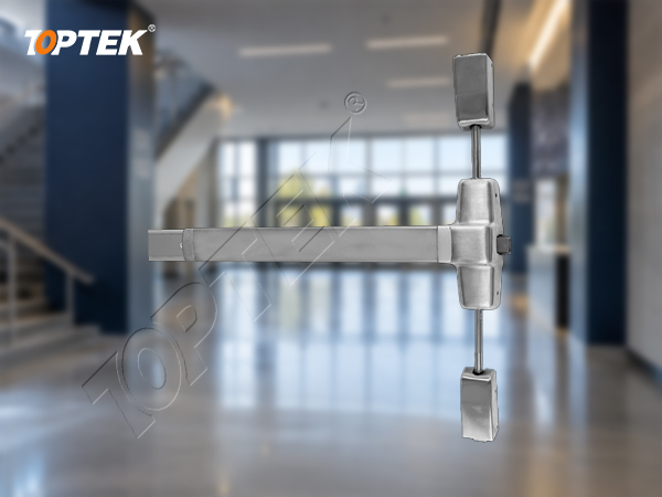
A device with vertical components needs a different collision check from a bar whose hardware is concentrated near the operating height. Look at the lower cover near skirting and floor-mounted objects, and the upper cover near projecting construction. Protecting the central bar alone does not protect the complete assembly.
For paired leaves, examine each permitted movement and the condition with both leaves open. A drawing with only one open leaf can overlook contact between opposing bars or outside trim. Where an opening has a prescribed operating sequence, retain it during the assessment and check the approved door assembly documentation before changing any coordinating hardware.
Leave practical access for removing a cover, reaching a fixing or servicing the device using its instructions. A stop that prevents collision may still obstruct a cover screw. Service access should be included in the shop drawing because relocating a stop later can leave unwanted holes or require new support in the door or surrounding structure.
Common mistakes and project risks
Using bar length as the clearance dimension. Length controls the span across the leaf; projection controls the space occupied away from its face. TOPTEK’s panic bar length selection guide addresses the first task. Record both dimensions for a complete opening review.
Setting the stop before the final hardware arrives. A temporary handle, sample cover or different trim can establish the wrong contact position. Mark the device and accessory revisions used during the trial and repeat the clearance check if the supplied configuration changes.
Solving a collision by limiting the opening without review. The change can affect passage width, circulation and the intended use of the doorway. Have the responsible project team review the opening requirement before accepting the new stopping position.
Allowing finishing work to consume the gap. New wall lining, a protection rail or a thicker floor finish can change the relationship. Give the finishing contractor the relevant envelope and check the completed condition before handover. Photograph the closest approach with the door position identified.
TOPTEK range and evidence for a coordinated selection
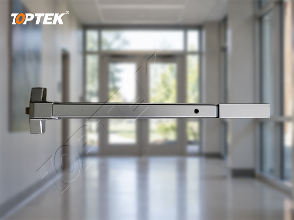
TOPTEK lists PEDAM001 and PEDAM002 panic exit devices. Use the selected product as the basis for requesting the installation envelope, accessory list and mounting details. The photographs help identify the assembly; they do not provide a dimensioned clearance approval.
Why involve TOPTEK during the opening review? The device question can be considered together with the door preparation, outside trim and other commercial door hardware in the schedule. A buyer can then obtain a quotation against one identified configuration rather than an assortment of independently selected parts.
Use the quality management information to structure requests for drawings, sample records and supplied-part identification. For fire or escape applications, request the exact device and assembly evidence required by the project. A dimensional fit, general catalogue statement or photo does not establish certification coverage.
RFQ checklist for projection and stopping details
- Door ID, destination market, intended use and applicable project requirements.
- Finished door and frame sections, leaf size, opening direction and hinge or pivot axis.
- Selected device, outside trim, rod configuration and mounting accessories.
- Required opening position and relevant passage or maneuvering-space review.
- Plan and elevation of walls, adjacent leaves, glazing and other potential obstructions.
- Proposed stop type, contact surface, fixing support and service-access needs.
- Representative sample plan, drawing revision, quantities and delivery schedule.
Send the opening plan for a device clearance review before finalising the stop location. Label the closest obstruction and show the direction in which the leaf moves.
Frequently asked questions
Is panic bar projection the same as bar length?
No. Projection is measured away from the mounting face, while length describes the span along the door. Both belong in the hardware schedule.
Can the door stop contact the push bar?
The touch bar should not be used as an improvised stopping surface. Coordinate the stop contact and support with the door and hardware instructions.
Is checking the fully open position enough?
No. The device must clear obstructions throughout the intended swing, including intermediate positions and the different heights occupied by its components.
Does a smaller projection prove accessibility compliance?
No. The complete opening still needs the applicable clear-width, maneuvering-space, operating and other project checks.
What should buyers send to TOPTEK first?
Send the door and frame drawings, selected device, hinge or pivot location, intended opening position and nearby obstruction details.
Confirm the opening before ordering
A dependable clearance decision connects the device envelope to the real door swing and the intended stopping arrangement. Preserve that relationship through sample review, installation and final finishing. Once the configuration and project requirements are agreed, request a formal quotation with the approved opening schedule.