

TL;DR
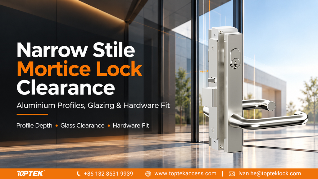
- Review the actual profile section, including glazing and reinforcement, rather than the visible stile width alone.
- Separate backset, lockcase envelope, fixing paths and trim footprint.
- Include installation and removal access; a component that fits in place may still be difficult to assemble or service.
- Confirm the door motion and function before comparing narrow-stile product dimensions.
Quick Answer: how much clearance does a narrow-stile lock need?
There is no single clearance value that applies to every narrow-stile mortice lock. Compare the exact lock drawing with the aluminium profile, glazing arrangement, reinforcement, trim and fasteners. Check the full case envelope, the spindle and cylinder interfaces, screw paths, lever movement and service access. Apply the clearances and preparation limits specified by the lock and door-system suppliers. A nominal stile width or short backset does not establish that the complete assembly will fit.
Begin with the door motion and the intended function
A hinged door, pivoted door and sliding door can use different locking arrangements. The receiving detail and bolt action matter as much as the available space. Identify whether the opening needs a latch, deadbolt or another specified function before choosing a compact case.
For example, dormakaba’s 950 and 951 product information distinguishes applications and a sliding-door locking arrangement within a short-backset range. That is a useful reminder to check door motion. It does not establish interchangeability with a TOPTEK lock or transfer another manufacturer’s dimensions to it.
Use the TOPTEK Australian mortice lock family to begin the product discussion. Then identify the exact configuration, its intended door arrangement and the matching trim. Do not let the category name substitute for a fit or compliance assessment.
Read the profile section as occupied space
The outside width of a stile is not an empty cavity measurement. A section can contain glazing pockets, screw races, webs, thermal breaks or reinforcement. Some features may extend continuously; others may occur only near a joint or fixing. The lock review needs the section at the proposed installation position.
Ask the door fabricator for the profile reference and revision. Include the glazing bead, glass position, gaskets and any reinforcement used at the lock. If different door types use the same visible profile but different internal components, treat them as separate arrangements until the fit review confirms otherwise.
Photographs are helpful for an existing door, especially when a profile reference is missing. They do not reveal every hidden feature. Have an authorised fabricator establish the internal arrangement before machining near glass or structural features. Do not remove a web or change a glazing detail merely to make a lock fit.
Check five separate fit envelopes
A useful review divides the assembly into five areas. This prevents a positive case-depth check from hiding a problem with a screw or lever. Mark each area on the profile drawing and identify the corresponding hardware drawing. Record the supplier’s required clearance rather than inventing a general allowance.
| Envelope | Include in the comparison | Typical question |
|---|---|---|
| Lockcase | Body depth, height, thickness, projections and forend seating | Does the full body fit without contacting a web or glazing component? |
| Operating interfaces | Spindle, cylinder, cam and associated components | Do their positions and travel match the selected lock? |
| Fasteners | Through-fixings, screw tips, mounting posts and reinforcement | Can each fixing follow its intended path without interference? |
| External furniture | Escutcheon, rose, lever movement and adjacent beads | Can the user operate the furniture without contact? |
| Assembly and service | Insertion direction, tool access and component removal path | Can the set be installed and later serviced as instructed? |
The fifth area is easy to overlook. A drawing may show all components in their final positions without showing how they get there. Ask the installer to review the sequence. A proposed solution that requires disturbing glazing for routine hardware service deserves explicit discussion before the profile is released.
Keep backset separate from case depth and usable stile width
Backset locates the operating centre relative to the lock’s face datum. Case depth describes a different extent. A short backset can help place the handle near the door edge, but it does not tell the buyer the total space needed behind the faceplate. Always compare the complete case outline.
TOPTEK’s product information lists a short-backset TKAU9000EC family and the TKAU6400 family with different configuration options. Request the exact drawing for the quoted variant. Do not scale a product photograph or use one family member’s body dimensions for another.
The Australian backset selection guide covers the 60, 89 and 127 mm family choices. Those values should not be used as dimensions for a narrow-stile proposal. This review instead starts with the specific profile cavity and selected short-backset configuration.
For a preliminary review, send the profile section and a marked handle position to TOPTEK. Ask which case outline, interface dimensions and trim drawing are needed to complete the comparison.
Coordinate glazing, trim and fixing paths on one drawing
Place the lock outline, trim footprint and fastener paths on the same section and elevation. Use a common datum so the door fabricator and hardware supplier can compare the same geometry. A trim plate that covers the preparation does not prove its mounting posts avoid the glass channel.
Check the lever’s movement and hand clearance with the selected trim. Nearby beads, applied bars or adjacent leaves may affect use even where the plate fits. Identify the actual lever design and orientation. Do not approve the furniture using only the lockcase drawing.
Reinforcement is another separate decision. Confirm the door-system supplier’s permitted fixing arrangement and preparation limits. A screw’s apparent ability to enter the profile does not establish its load path or suitability. Keep mounting requirements with the hardware schedule rather than leaving the fabricator to infer them from a product image.
For an electrically operated variant, add the connector envelope and cable route to the review. Do not assume the cable space is identical to that of a mechanical version. Obtain the actual configuration drawing and wiring requirements before preparing a route through the profile.
Use a fit matrix to manage unresolved details
A fit matrix lets the buyer distinguish a confirmed dimension from a missing drawing. Use one row for each interaction, not one overall tick for the whole door. The following format can be copied into the project review sheet. Leave the result unresolved until the responsible supplier has provided the necessary information.
| Interaction | Evidence to compare | Record before release |
|---|---|---|
| Case to profile | Lock outline and profile section at the installation height | Clearance assessment and drawing references |
| Forend to door edge | Forend drawing and permitted recess detail | Seating and fixing arrangement |
| Fixing to glazing | Fastener path and glass or bead position | Confirmed separation and responsible reviewer |
| Trim to bead | Furniture footprint, lever motion and bead geometry | Fit and operating-space result |
| Bolt to frame | Lock function and receiving detail | Engagement and operation result |
| Removal to access | Installation sequence and service instructions | Tool access and component removal method |
An illustrative review might confirm the case envelope but leave the trim fixing path unresolved. The correct next step is to obtain the trim drawing, not to describe the whole lock as fitting. This approach makes outstanding decisions visible without assigning a false clearance value or changing the profile by guesswork.
Validate a representative assembly and avoid common shortcuts
Use a sample profile with the specified glazing arrangement, reinforcement, trim and receiving hardware. Check assembly access, seating and operation. Retain photographs of the preparation before the components hide it. Record the exact sample configuration and any agreed drawing changes.
Do not approve an empty extrusion sample when the production profile will contain additional parts. Similarly, a trial with a different trim set cannot establish the proposed fastener clearance. If the supplier changes a mounting post, case outline or connector, review the affected matrix rows again.
Common shortcuts include selecting by visible stile width, confusing backset with total body depth, and treating a covered preparation as a correct preparation. These can lead to unusable parts, machining rework or difficult servicing. A coordinated section and sample check address the cause before a repeated production error develops.
For a fire, security or escape-door application, confirm the exact documented assembly and permitted preparation. Physical fit alone does not establish a rating or approval. Request evidence for the specific model and intended application instead of relying on a general product-family description.
TOPTEK product scope and a quotable RFQ package
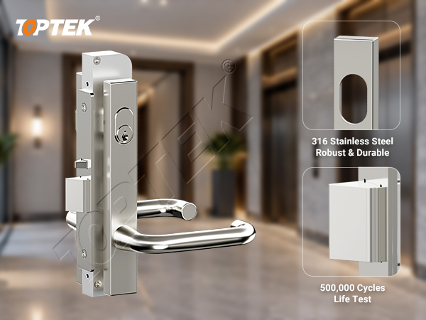
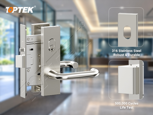
The TKAU9000EC product reference provides the narrow-escutcheon starting point shown here. The TKAU6400EC image below illustrates another family presentation for comparison. These product images identify assemblies; they do not establish common case dimensions, trim interchangeability or suitability for a particular extrusion.
Why TOPTEK? A configuration enquiry can bring the lock, trim and document requirements together before sampling. Review the quality management information and ask which dimensional inspection records apply to the proposed order. Keep the accepted sample linked to the final bill of materials.
- Door motion, function, location and quantity.
- Profile identifier, current section and glazing arrangement.
- Selected lock variant, case drawing and intended handle position.
- Trim, cylinder, spindle, fasteners and reinforcement details.
- Receiving hardware, installation sequence and service access.
- Electrical interface where applicable, evidence requirements and sample acceptance criteria.
Frequently asked questions
Can visible stile width determine narrow stile mortice lock clearance?
No. Internal webs, glazing components, reinforcement and fixing paths can occupy the space behind the visible face. Review the complete profile section.
Does a short backset guarantee a shallow lockcase?
No. Backset and case depth describe different dimensions. Use the exact variant’s full case outline to assess available space.
Can a hinged-door lock be selected for a sliding door by size alone?
No. Door motion, bolt action and the receiving arrangement must suit the application. Confirm the intended function before comparing dimensions.
Why should the trim drawing be reviewed with the lock drawing?
Trim plates, mounting posts and fasteners occupy additional space. Their fit and operating clearance cannot be established from the lockcase outline alone.
What information helps when the profile drawing is missing?
Provide the door-system name, profile markings and clear photographs. Ask the fabricator to identify the internal section before any machining decision.
Request a profile fit review and quotation
A reliable narrow-stile order connects the profile, lock, trim and installation method. Complete the fit matrix, retain the sample evidence and review changes before production. For a commercial door hardware project, send the profile package and quantities to ivan.he@toptekaccess.com. Request a configuration proposal, the relevant drawings and a sample quotation.