
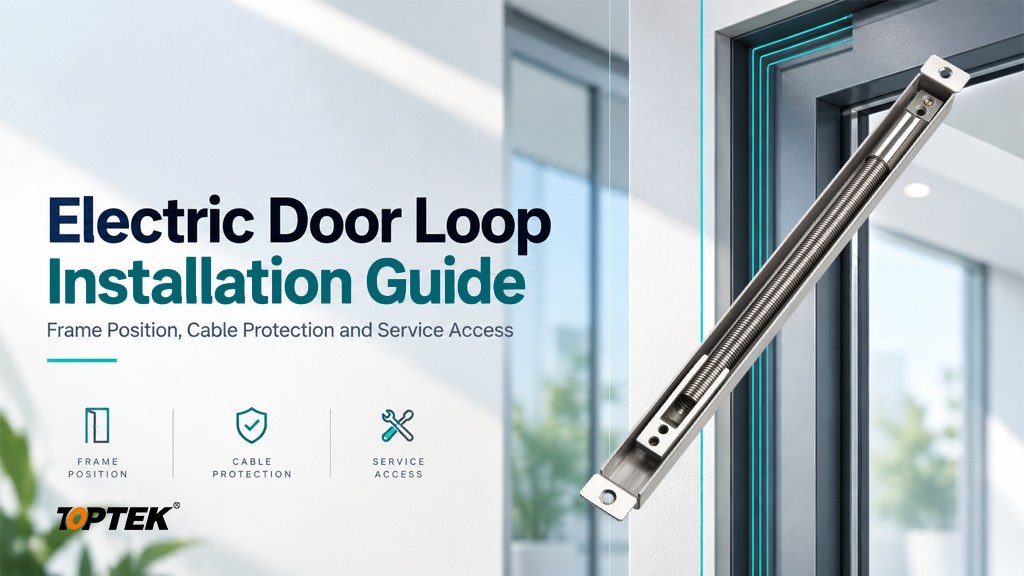

TL;DR
- Select the mounting position from the actual door, frame and hinge geometry.
- Use the chosen model’s preparation drawing; overall size is not a routing template.
- Protect cable entries, provide the specified strain relief and respect cable bend limits.
- Check the full opening travel and the final closing movement before electrical commissioning.
- Leave a documented service route so a cable can be inspected or replaced without unnecessary damage.
Quick Answer
Plan electric door loop installation by identifying the model, mounting method, cable and full door travel before cutting or drilling. Choose a position where the loop can flex without stretching, trapping the cable or touching other hardware. Prepare the door and frame to the applicable drawing, protect cable-entry edges and secure the cable as specified. Check movement at closed, intermediate and fully open positions, then test the electrical circuit using the connected equipment’s instructions. For a rated door, confirm that the preparation and cable route are permitted by the doorset evidence. Record the final position and accessible service connections.
Confirm what must cross from the frame to the leaf
A door loop provides a route for a cable between a fixed frame and a moving leaf. Start by confirming that the powered or monitored device actually needs that crossing. A frame-mounted device may have a different routing requirement from a lock or sensor mounted in the leaf. Trace the proposed circuit before choosing the transfer assembly.
List the cable’s outside diameter, conductor arrangement, flexibility, environmental suitability and required bend radius. Also record the connected equipment, supply requirements and any signal separation instructions. The loop’s metal body does not define the cable’s allowable current or make an unsuitable cable suitable for repeated flexing.
The TOPTEK hinges and door power transfer range includes loop assemblies and electric hinge options. Use the electric hinge and door loop comparison if the transfer method has not yet been selected. Once a loop is chosen, its installation detail should be resolved for the actual opening.
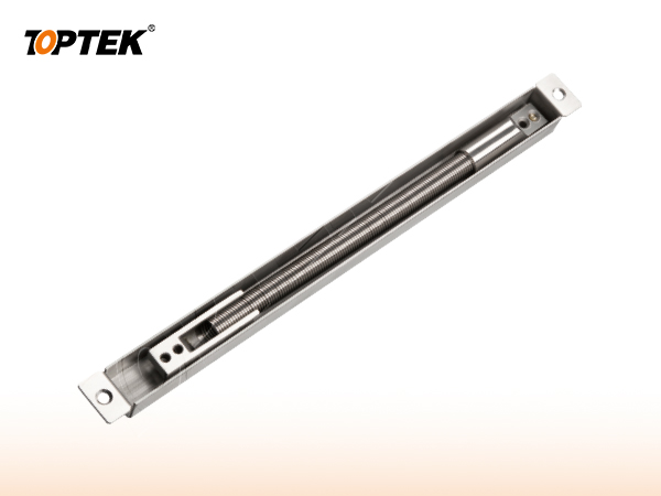
Choose the position by checking the entire movement
The mounting position needs enough space for the assembly throughout the opening arc. Inspect the hinge pivot, frame rebate, door edge, seals and adjacent hardware. A small shift in location can change how the cable bends or how the moving section enters its housing, so a generic offset should not be copied between different openings.
Before permanent preparation, use the model drawing and a controlled trial arrangement to check the proposed position. Observe the door closed, partly open and at its intended maximum travel. Look for tension, twisting, compression, contact with sharp edges and interference with the final closing movement. Check both the housing and the cable path inside it.
Do not use the loop as a door stop. The door’s permitted opening angle and physical stop must be coordinated with the transfer assembly’s limits. If the selected position cannot accommodate the required travel, revise the arrangement or select a suitable alternative before preparing the door.
Check practical access as well as movement. Can the installer reach the fixings without removing unrelated hardware? Can maintenance staff reach a connector or inspect the cable entry later? A technically possible position can still create unnecessary service work if its fasteners are hidden behind a fixed panel.
Turn the model drawing into a preparation checklist
Overall product dimensions do not define the recess, hole positions or cable-entry route. Obtain the installation drawing for the precise model and revision, then check it against the door and frame sections. Mark the reference surfaces clearly so the factory and site installer use the same location.
| Preparation item | Check before machining | Acceptance evidence |
|---|---|---|
| Housing or mounting base | Model, orientation and required depth | Drawing reference and measured preparation |
| Fixing locations | Edge distance, reinforcement and fastener type | Door and frame fixing detail |
| Cable entries | Clear route, edge protection and bend space | Entry photographs and cable specification |
| Moving section | Travel through the intended opening arc | Movement check at several door positions |
| Service connections | Accessible location and cable identification | As-installed connection record |
For a metal frame, confirm the fixing support and the hidden space available behind the prepared surface. For a timber door, confirm the construction at the proposed recess and the permissible preparation. Do not assume that a photograph of a similar door demonstrates the same internal structure.
For fire or smoke doors, obtain the applicable doorset detail before cutting new cable passages or enlarging a recess. The acceptance question is whether that preparation is permitted for the assembly. A product-family claim or a test associated with a different hinge cannot establish permission for a door loop installation.
Protect the cable at entries and moving sections
The cable should move within its intended flexing region without being pulled against a terminal or cut by an entry edge. Remove machining debris, inspect the route and fit the specified bushes or protective features. Leave the required working length without adding uncontrolled loops that can snag or become compressed inside the housing.
Follow the loop and cable instructions for routing and retention. A tight tie placed in the wrong location can move the bending stress to a vulnerable point. Similarly, excess cable pushed into a narrow recess can interfere with closing even when the visible loop moves freely.
Manufacturer instructions are specific to their own products. For example, the ASSA ABLOY cable-loop catalogue describes routing and preparation conditions for its named loop models. It illustrates why flexible cable, protected entries and room for movement matter. Its dimensions and limits should not be transferred to TOPTEK assemblies.
Keep splices and connectors in locations allowed by the equipment instructions and accessible for service. Identify both ends of the cable. Confirm that screen or shield termination, where used, follows the system design rather than an assumption that the loop housing automatically provides an electrical connection.
Install, inspect movement and commission the circuit
Installation should proceed with the electrical circuit isolated and the door safely controlled by competent personnel. Follow the selected assembly instructions for the order of cable routing and fastening. Before final closure of covers, inspect the hidden cable path and confirm that fixings do not contact or compress the cable.
- Check the model and drawing revision against the work instruction.
- Inspect the preparation, fixing support and protected cable entries.
- Route and retain the specified cable without twisting or forcing it.
- Secure the assembly with the correct fixings and specified tightening method.
- Move the door through its full permitted travel and inspect the return movement.
- Check continuity and circuit connections using methods appropriate to the equipment.
- Restore power and verify the connected functions under the agreed commissioning procedure.
- Record the installed position, cable identification and service access.
Do not apply an electrical test that could damage connected electronics. The equipment instructions should determine whether components must be disconnected and which test method is appropriate. A simple successful unlock command also does not demonstrate that the cable remains protected during every door movement.
Observe the assembly again after the door has completed several normal operating movements. Look for rubbing, unexpected noise, loose retention or cable movement at a fixed connection. If a problem appears at only one angle, record that position. It provides a useful starting point for correcting the geometry.
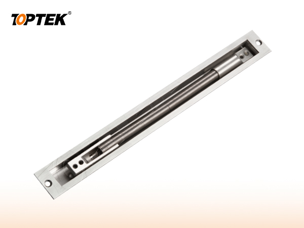
Common installation faults and service checks
A loop that reaches tension before the door reaches its stop needs a geometry or product-selection review. Adding a longer cable does not necessarily correct a housing or transfer mechanism that has reached its travel limit. Inspect the whole assembly, including the way the cable enters each end.
A loop that interferes during the final closing movement may have insufficient recess clearance, misplaced entry holes or excess cable inside the housing. Correct the cause according to the permitted preparation. Do not force the door closed or remove protective components simply to obtain more space.
Intermittent electrical operation during movement can indicate a damaged conductor or strained connection, but the diagnosis should include the complete circuit. Record the door position, connected load and symptom, then isolate the cause using the equipment instructions. Replacing the controller without checking the moving cable path may leave the original problem unresolved.
For maintenance, include the loop in the door inspection routine. Check retention, visible cable damage, entry protection and freedom of movement. Use the manufacturer and project requirements to set the interval. Keep the as-installed photographs and cable record available to the service team so that replacement work preserves the intended routing.
Why TOPTEK for door power transfer coordination?
TOPTEK lists Electric Door Loop 01 and Electric Door Loop 02 as distinct product references. Compare their housing geometry using the current drawings rather than selecting only by appearance. Ask for the cable suitability, preparation detail and movement limits that apply to the quoted configuration.
TOPTEK’s commercial lock and access control manufacturing overview explains its locking-hardware scope and interface coordination. For the installer, the useful output is a compatible physical arrangement linking the chosen lock, cable route and door construction. The access-control system requirements still need to come from the responsible integrator.
The TOPTEK quality management overview provides a route to discuss configuration identification and inspection records. Request the drawing revision and supplied-parts list with the sample. For an initial layout review, send a hinge-side section, door travel requirement and cable specification before authorising machining.
RFQ checklist for an installation review
- Door and frame material, section drawings and hinge or pivot arrangement.
- Required opening angle, stop location and clearance constraints.
- Selected loop reference, finish, quantity and sample requirement.
- Cable outside diameter, construction, bend limit and environmental requirements.
- Powered device, circuit requirements and service connection location.
- Permitted preparation and applicable rated-door documentation.
- Fixing support, installation responsibilities and commissioning records.
Ask the quotation to distinguish the loop assembly, cable, connectors and installation accessories. This prevents a common purchasing gap: the project receives the transfer hardware but assumes that all electrical components are included. Confirm the supplied scope before comparing prices or scheduling site installation.
Frequently asked questions
Where should an electric door loop be installed?
Use the selected model’s installation drawing and the actual door geometry. The position must permit full movement, protect the cable and allow access to required fixings and service connections.
Can overall dimensions be used as a recess template?
No. Obtain the model-specific preparation drawing. Overall dimensions do not establish recess depth, fixing centres, entry positions or permissible door preparation.
Does a metal loop determine the cable current rating?
No. Confirm the cable and connected equipment requirements separately. The loop protects the route but does not establish conductor size, allowable current or signal compatibility.
Can a door loop act as the door stop?
No. Coordinate a suitable door stop with the permitted travel of the loop. The transfer assembly should not be used to arrest the opening door.
What should be checked before fitting a loop to a fire door?
Confirm that the selected assembly, recesses, cable passages and fixings are permitted by the applicable doorset evidence and instructions before making alterations.
What information helps TOPTEK review an installation?
Provide the door and frame sections, hinge geometry, required opening travel, cable specification, selected loop reference and any rated-door constraints.
Request a door loop installation review
Good installation keeps the cable protected through every permitted movement and leaves a clear route for maintenance. Resolve the drawing, preparation and service details before machining, then verify the installed motion and circuit together. Send your door sections and cable requirements to ivan.he@toptekaccess.com to request a configuration review, sample proposal and formal quotation for the required quantities.