

TL;DR
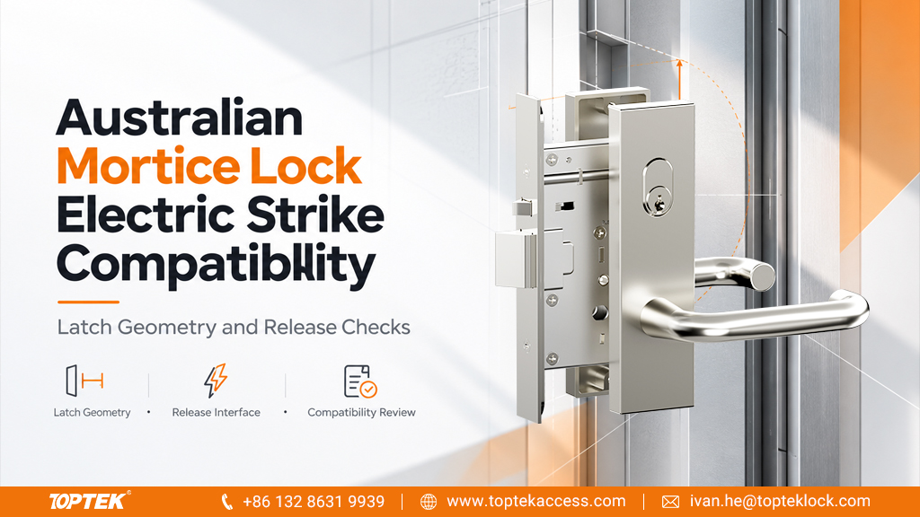
- Confirm the exact mechanical mortice lock and electric strike as one proposed combination.
- Review latch geometry, auxiliary contact, frame space and the intended release path.
- Specify the required door operation separately from the strike’s electrical settings.
- Demonstrate release and relatching on the intended opening before accepting a repeated configuration.
Quick Answer
Australian mortice lock electric strike compatibility depends on the exact lock function, latch arrangement, strike geometry and installed door conditions. An electric strike releases a frame-side keeper; it does not automatically change the mechanical lock’s lever or deadbolt function. Obtain both manufacturers’ applicable drawings and confirm the proposed combination, including any auxiliary latch contact and projected deadbolt condition. Then have the responsible installer and integrator verify the agreed operating sequence on the assembled opening. A shared regional product description or matching faceplate length is not enough to establish compatibility.
Define what the strike is expected to release
Start by describing the access sequence in plain language. For example, the project may require a credential to release the frame-side keeper so an authorised user can open a door fitted with a mechanical mortice lock. Write down what the outside handle does before and after that command, and how the inside handle operates independently.
The lock and strike perform different jobs. The mechanical lock controls its own latch and lever behaviour. The strike controls the frame-side retaining element specified by its design. A command to the strike should not be assumed to retract a lock bolt or change a locked lever to an unlocked lever.
Identify the mechanical configuration within the TOPTEK Australian mortice lock range. TOPTEK also describes motorised and solenoid platform options, but those are separate configuration discussions. This guide concerns the proposed interface between a mechanical assembly and an electric strike; it does not assume that adding a strike converts the lock itself into an electrified version.
Compare the latch geometry with the keeper
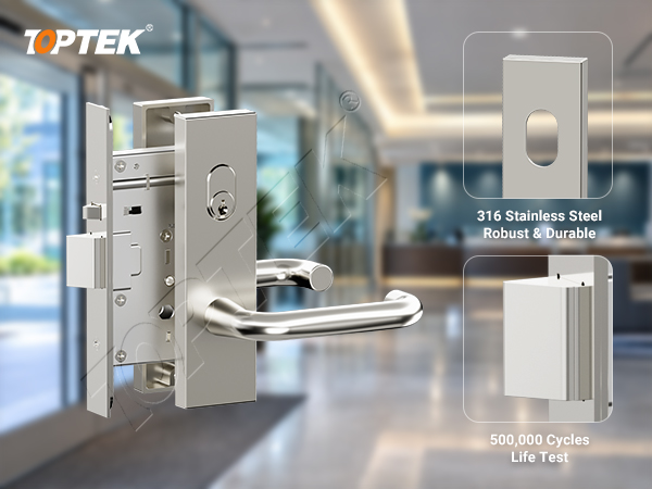
Request the latch projection, position and relevant profile from the lock drawing. Compare them with the receiving space and moving keeper shown in the strike documentation. Include the installed relationship between the door edge and frame, using the applicable gap and alignment instructions rather than a generic allowance.
Where the lock includes an auxiliary component, confirm how that component should meet the strike. Its contact requirement may differ from the main latch’s receiving requirement. Ask the manufacturers to identify the correct arrangement for the proposed pair. Do not assume that making the receiving pocket larger improves every part of the interface.
Lockwood’s ES2000 product specification states its latch suitability with an associated door-gap condition. This is a useful example of why the two dimensions must be considered together. Those values belong to that product; they are not a TOPTEK compatibility statement or a universal strike specification.
If a separate deadbolt is present, include its projected state in the discussion. Do not assume that the proposed strike can release or receive it. The agreed access sequence must explain how each relevant bolt state affects opening and closing. Resolve this before choosing a strike solely by voltage or appearance.
Check the frame and the path of the moving parts
The frame needs space for the strike body, the keeper movement and the documented fixing arrangement. Obtain a section through the frame as well as a front elevation. Reinforcement, a rebate, a stop or nearby construction may affect the available space even when the faceplate appears to fit.
Consider the path during opening, not only the closed position. The released keeper and the latch need the clearance specified for that assembly. The installer should review this against the actual swing and frame arrangement. A comparison of two front-view photographs cannot establish the full movement path.
Ask the responsible door or frame supplier to identify any permitted preparation work. An existing frame may require a different assessment from a new frame manufactured for the strike. Keep machining and reinforcement responsibilities explicit in the quotation so an electrical installer is not left to make an undocumented structural decision.
For a fire-resisting or otherwise specially assessed doorset, obtain the evidence applicable to the complete proposed arrangement before changing the frame. A product-level statement on either component does not, by itself, establish the acceptability of that particular door assembly.
Use a clear mechanical and electrical interface matrix
Assign each question to the party that can answer it. The lock supplier identifies the mechanical assembly, the strike supplier identifies the keeper and electrical product, and the integrator connects the agreed operation to the control system. The door supplier addresses the construction and preparation.
| Interface question | Evidence to request | Responsible coordination |
|---|---|---|
| What retains the closed door? | Lock function and relevant bolt states | Lock supplier and project specifier |
| What does the strike release? | Keeper drawing and product application limits | Strike supplier |
| Does the geometry fit? | Combined latch, strike and frame drawings | Hardware suppliers and door manufacturer |
| What happens on a command or power loss? | Agreed operating sequence and electrical configuration | Integrator and responsible project team |
| What does each signal report? | Monitor contact definitions and system mapping | Strike supplier and integrator |
| How is the result accepted? | Installed test plan and configuration record | Installer and designated acceptance authority |
Keep electrical compatibility specific. Record the selected strike’s supply requirements, control method and operating duty from its documents. A suitable controller output does not establish mechanical compatibility, and a mechanically suitable strike still needs a correctly specified supply and control arrangement.
Account for preload and useful monitoring
Preload describes force already acting on the keeper before release. It can make the installed condition different from a freely moving bench sample. Record relevant door behaviour and ask the strike supplier whether the proposed product is suitable for that condition. Do not infer a release-under-load capability from a general holding-strength statement.
Lockwood’s ES9000 preload guidance identifies examples such as a user pulling before release, door condition, seals and pressure differences. It supports including preload in the selection discussion. Its stated ratings remain specific to the ES9000 and should not be assigned to another strike or TOPTEK lock.
Define monitoring signals by what they actually sense. A signal associated with a strike’s solenoid or keeper is not automatically proof that the door leaf is closed or that every lock component is secure. Ask for the contact definitions and map them to the controller’s displayed states without changing their meaning.
Where the project requires door position, identify the actual sensing arrangement and its relationship to the installed opening. Keep command, component state and door position separate in the test record. This helps distinguish an electrical command that was issued from a mechanical action that was completed.
Review the intended operating sequence on the opening
Use an identified sample with the selected mechanical lock, strike, frame preparation and control configuration. The competent installer and integrator should follow the relevant product instructions and the project’s agreed test plan. Retain the component references and settings with the results.
Record the closed condition, the authorised release event, opening and subsequent relatching. Include the handle actions expected from each side. Where the agreed function includes other bolt states, verify those states as part of the plan. Avoid declaring the combination accepted after observing only an audible click from the strike.
The responsible project team should define the required behaviour during loss and restoration of power. Confirm it against the exact hardware configuration and applicable project requirements. The strike’s fail-safe or fail-secure label alone cannot describe the complete door’s access and exit behaviour.
If the result changes with door position or pressure, record that observation and request assessment. Do not compensate by increasing electrical input beyond the product instructions or altering the latch. A useful service record names the condition, the expected result and the observed result so the responsible supplier can investigate.
TOPTEK product scope and the value of a coordinated enquiry
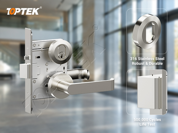
TOPTEK’s current Australian references include TKAU6400EC escutcheon trim and TKAU6400RR round rose trim. Identify the full mechanical assembly behind the selected trim. Neither trim reference by itself establishes compatibility with a named third-party electric strike.
TOPTEK describes first-piece, patrol and sampling controls in its production information. Its quality management resources can support a discussion about product identification and inspection records. For this application, ask which drawings and configuration documents apply to the proposed lock.
Why TOPTEK for the lock-side discussion? Buyers can begin with an identifiable product family and coordinate its mechanical requirements with a named strike proposal. A useful supplier response should clarify the offered assembly and the evidence needed to review the interface. It should not replace the strike supplier’s application limits or the integrator’s system design.
RFQ checklist for a proposed lock and strike combination
- State the complete mechanical lock function and preferred trim.
- Name the proposed electric strike and include its current documents.
- Provide door and frame drawings, swing and preparation information.
- Describe latch and auxiliary contact requirements, including any deadbolt states.
- Set out the intended entry, exit, release and relatching sequence.
- Identify electrical supply, control and monitoring requirements.
- State sample review, evidence, quantities and substitution responsibilities.
Use the Australian mortice lock door schedule guide to keep the opening identity and required operation consistent. Attach the strike documents to the same schedule so mechanical and electrical purchasing do not proceed from separate assumptions.
Where several suppliers participate, ask the quotation to identify what is included and what must be supplied by others. TOPTEK’s commercial door hardware manufacturing information provides broader sourcing context. The final purchase record should still name the exact combined configuration and the evidence used to accept it.
Frequently asked questions
Will any electric strike work with an Australian mortice lock?
No universal compatibility should be assumed. Confirm the exact lock function, latch and auxiliary geometry, strike design, frame preparation and installed operating requirements.
Does an electric strike retract the mortice lock latch?
An electric strike releases its frame-side keeper according to its design. Do not assume that it retracts the lock latch or changes the mechanical lever function.
Can a projected deadbolt be ignored during selection?
No. Include every relevant bolt state in the compatibility review and operating sequence. Confirm whether the specific strike can accommodate the required condition.
Does a strike monitor prove that the door is closed?
Only if the documented sensing arrangement supports that meaning. Confirm what each contact actually reports and specify a door-position signal separately where needed.
What is needed before repeating an accepted combination?
Retain the lock, strike, frame and control configuration with the installed review result. Reassess changes to those components or conditions before applying the record to another opening.
Request a compatibility discussion or a project quotation
A reliable procurement decision connects the mechanical lock, moving keeper, frame and intended operating sequence. Establish those interfaces together and retain the confirmed combination for installation and repeat orders.
Send the proposed lock and strike documents for an initial discussion. Include the opening drawing and required operation from each side.
Request a formal project quotation with the agreed mechanical configuration, quantities and required supporting documents.