

TL;DR
- Confirm whether the exact solenoid and control arrangement permit continuous or intermittent energisation.
- Translate the access schedule into electrical on-time, maximum hold time and repeated operation.
- Separate controller command duration from the power actually applied to the coil.
- Evaluate heat and operation in the representative door assembly, using documented acceptance limits.
Quick Answer
Solenoid mortise lock duty cycle is the permitted pattern of electrical energisation for a specified lock and operating condition. A continuous-duty rating permits sustained energisation within the manufacturer’s stated limits. An intermittent-duty specification requires defined on-time and recovery conditions. Neither label can be inferred from voltage or from fail-safe and fail-secure terminology. Ask for the exact model’s electrical data and compare them with normal access, scheduled entry periods, repeated commands and power restoration. Verify the complete controller, supply and lock combination before applying the intended schedule.
Define duty cycle without confusing it with access frequency
For a repeating electrical pattern, duty cycle can be expressed as on-time divided by the complete on-and-off period. This ratio helps describe operation, but it is not a complete thermal specification. The maximum uninterrupted on-time, ambient conditions and recovery requirements also matter.
For illustration only, energising for five seconds in a twenty-second cycle gives a 25 percent on-time ratio. Energising for five minutes in a twenty-minute cycle gives the same ratio. Those examples do not establish equivalent heating or acceptable operation for a lock. They demonstrate why the duration of each interval must accompany the percentage.
Door traffic counts answer another question. A frequently used door may involve short electrical release periods, while a lightly used door may remain energised for a long scheduled mode. Start with the actual electrical behaviour, not a description such as “high traffic” or “commercial duty.”
TOPTEK’s electronic lock and access control range includes motorized and solenoid-controlled platforms. Identify the selected mechanism before discussing duty. A motor-driven movement and a solenoid-held condition can require different control and power information.
Identify what the solenoid changes inside the lock
A solenoid-controlled lock may use electrical action to change engagement within the mechanism. The resulting door behaviour depends on the particular design. Establish whether the command enables a handle, changes a locking condition or operates another approved function. Do not assume that applying power always retracts every latch and bolt.
The outside entry function and the inside exit function must be described separately. A power-state label does not fully describe egress or mechanical override. Use the manufacturer’s function documentation and project requirements to record what each side of the opening does in each relevant state.
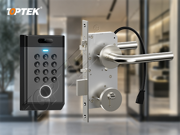
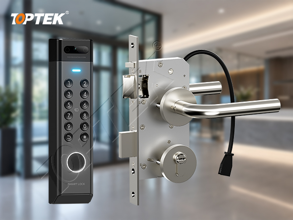
For a TOPTEK enquiry, the TKAMSRR9200RR solenoid-controlled platform provides a concrete product reference. Confirm the configuration suffix, operating function and electrical documentation for the proposed supply. A family reference alone does not define every available electrical option.
Distinguish continuous duty from a controller hold command
A continuous-duty rating belongs to a defined product operating under stated conditions. It does not mean that any voltage, waveform or installation environment is acceptable. Intermittent duty similarly needs specific limits rather than a general instruction to avoid leaving the power on.
ASSA ABLOY’s AM1000 product documentation explicitly identifies continuous-duty solenoids. This is an example of the type of model-specific statement a buyer should request. Its published electrical values and options apply to that product, not to TOPTEK models or to solenoid locks generally.
A controller may maintain a release signal while electronics within a compatible lock regulate the electrical drive. Another arrangement may apply power directly through an approved switching path. Ask which arrangement the selected product uses. A command lasting ten minutes does not, by itself, reveal the coil’s power profile.
Do not add a power-reduction circuit or alter a waveform without the manufacturer’s instructions. A modification that changes heat generation can also change actuation, holding behaviour, monitoring or return to the required state. Evaluate the complete supported control arrangement.
| Item to confirm | Documented answer needed | Purchasing implication |
|---|---|---|
| Permitted electrical input | Voltage, polarity and any approved input form | Select a compatible supply and control output. |
| Duty and maximum on-time | Continuous or defined intermittent operation | Check scheduled access and repeated release commands. |
| Operating and holding demand | Applicable current values and timing | Allow for the actual electrical load profile. |
| Ambient and installation limits | Manufacturer’s stated conditions | Review the intended door and enclosure environment. |
| Acceptance criteria | Defined temperature and functional checks | Use a measurable sample evaluation procedure. |
Turn the access schedule into electrical operating cases
List the normal release duration, scheduled access modes, expected bursts of use and any command that can remain active. Include the behaviour after a controller restart and after power restoration. The goal is to understand the longest credible energisation period as well as the usual one.
Consider a lobby opening with credential entry outside business hours and a scheduled entry mode during staffed hours. The hardware designer should identify how each mode is achieved. Do not assume that the longer mode is supported simply because brief credential releases work during a demonstration.
For repeated commands, check whether the controller restarts, extends or queues the release period. Two systems with the same nominal release setting can create different cumulative on-time. Record the configured behaviour and verify it with the actual control equipment.
Use a schedule that identifies the command source, expected duration, electrical response and final door state. Keep this record with the configuration settings. If the building later changes its access hours, the facilities team can check the new schedule against the approved operating limits.
Assess heat and electrical supply in the representative assembly
A bench demonstration can confirm a basic function, but the installed environment may change how heat is managed. Evaluate the agreed duty pattern with the specified lock, trim, door construction and control equipment. Record ambient conditions and follow the manufacturer’s procedure for measuring any relevant temperatures.
Do not define acceptable heat by touch alone. Request the manufacturer’s limits and measurement locations. Investigate unexpected heating, delayed operation, inconsistent release or failure to return to the intended state using the approved service procedure. A warm housing is not enough evidence to declare either a failure or a successful thermal assessment.
Supply selection must account for the actual load, cable route and simultaneous operation where relevant. Measure at the location specified by the manufacturer while the hardware operates. The electronic mortise lock wiring guide covers related conductor and power-transfer planning. Duty review adds the duration and sequence of that electrical demand.
- Record the lock reference and control configuration before testing.
- Confirm the approved supply and wiring arrangement.
- Run the agreed normal and extended operating cases.
- Record electrical and thermal observations against defined limits.
- Check entry, relatching and the required exit function after each relevant case.
Keep product evidence and system responsibility clear
TOPTEK’s electronic product information distinguishes solenoid-controlled and motorized mechanisms, with configuration-dependent interfaces and operating functions. Its electronic engineering capability supports discussion of the lock, control electronics and integration requirements. Use that discussion to obtain model-specific limits and an agreed evaluation plan.
Internal development testing and a third-party product report serve different purposes. Request the source, scope and specimen identity of any test result offered for the project. A report addressing mechanical durability does not necessarily establish the permissible electrical duty for every controller configuration.
Assign responsibility for the supply, controller settings, wiring, lock configuration and commissioning record. This prevents the lock supplier from assuming one release schedule while the integrator implements another. Preserve the settings and document revisions used in the accepted sample.
Common errors include equating fail-safe with continuous duty, using nominal voltage as the only compatibility check, and extending a pulse setting to an all-day access mode. The resulting risks include overheating, unreliable operation and disputes over which configuration was evaluated. Resolve them through specific electrical documentation and controlled settings.
Prepare a duty-cycle RFQ and review request
Why TOPTEK? TOPTEK brings mechanical lock development and electronic engineering into the same product discussion. For an integrator or door manufacturer, that provides a route to review the intended operation, select a candidate platform and define the information needed for system evaluation.
For an initial review, send the desired access schedule, door application and available controller information. For a formal quotation, add the exact function, candidate model, supply details, expected maximum command duration, repeated-use pattern, environment, monitoring requirements and required test documents. Identify any existing hardware that the new lock must retain.
Request a response stating the supported control method, applicable duty limits, electrical data and proposed sample checks. Start the enquiry through TOPTEK’s commercial locks and access control manufacturing page. A clear timing schedule is more useful than asking only whether the lock is suitable for heavy use.
Frequently asked questions
Does fail-safe mean continuous duty?
No. Fail-safe describes a power-loss behaviour for the specified function. Continuous duty describes permitted energisation under stated conditions. Confirm both independently.
Can I calculate suitability from the duty-cycle percentage alone?
No. Maximum uninterrupted on-time, recovery conditions, ambient limits and the supported electrical drive also matter.
Does a long release command always keep the coil fully powered?
Not necessarily. The supported controller and lock electronics determine the electrical response. Ask for the actual drive arrangement and timing.
Can another manufacturer’s continuous-duty rating be used for a TOPTEK lock?
No. Electrical ratings apply to the identified model and configuration. Request TOPTEK documentation for the proposed assembly.
What information should an integrator send first?
Send the intended access schedule, lock function, controller output details, supply arrangement and door environment, including any extended release mode.
Match the electrical duty to the real opening
A solenoid mortise lock duty cycle review connects product limits to the way a building actually uses its doors. Define the electrical pattern, request the exact model’s data and evaluate the supported assembly under representative conditions. Keep those records with the access-control configuration so that later schedule changes can be assessed consistently.