

Electronic Mortise Lock Wiring Guide: Voltage Drop, Door Power Transfer, Conductors and Connector Planning
TL;DR
Electronic mortise lock wiring should be designed as a complete point-to-point circuit from the approved power supply and controller through the frame-to-door transfer to the exact lock and monitoring contacts. Confirm model-specific voltage, current, duty, polarity, conductor count and connector pinout. Check voltage at the lock under the worst expected normal operating condition; a nominal supply label alone does not prove adequate delivery.
Start with the Electronic Lock and Access Control product hub, then use this narrower guide to define the required function and approval evidence.
Quick Answer
Freeze the exact lock configuration and wiring document first. Build a conductor schedule for actuation, common/returns and every required monitoring point. Select a door power transfer that supports the conductor count and full door movement. Document connector pinouts and test loaded voltage, operation, monitoring, power loss and mechanical override on the commissioned opening.
Draw the whole circuit before selecting cable
The circuit begins at the approved supply and control output, crosses fixed building wiring, reaches the frame, passes through an electric hinge, concealed transfer or protected loop, and terminates at the lock and any trim or monitoring contacts. Every transition needs an opening number, cable identity, termination point and responsible trade.
A product schedule that says only “electronic mortise lock” leaves the controller, relay, supply, transfer and conductors undefined. Create a point-to-point diagram and cable schedule before the door or frame is machined. Use the same opening number on architectural, door-hardware, access-control and electrical documents.
Use exact model electrical data
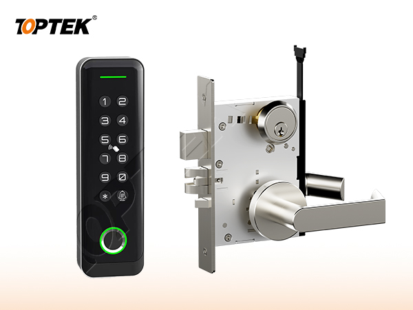
Voltage, current, duty, polarity, actuator type, monitoring-contact ratings and connector assignments can differ by model and option. TOPTEK internal material describes motorized and solenoid-controlled electronic mortise-lock families, but this guide does not publish a universal value. Request the current wiring information for the exact quoted configuration.
Separate actuator power from signal contacts in the schedule. Note inrush and holding behaviour when the current model document specifies them. Confirm whether the control output switches the supply directly or operates a suitable relay. The responsible system designer must validate the complete circuit and applicable electrical practice.
Plan for voltage drop under load
Cable resistance and connection losses reduce the voltage available at the lock when current flows. Longer routes, smaller conductors, additional connectors and poor terminations can increase the loss. Measure or calculate using the approved design data, then verify at the lock while the device performs the highest relevant normal electrical demand.
An unloaded meter reading can look correct even when the voltage falls during actuation. Record supply voltage, loaded voltage at the opening, cable length, conductor size, connection path and operating state. Do not raise the supply setting beyond the model limit to compensate for an unresolved cable problem.
Coordinate the moving-door power transfer
The frame-to-door transfer must carry the required number and type of conductors through the complete door swing without pinching, excessive bending or conflict with hinges, reinforcement, seals or fire-door preparation. A concealed transfer, electric hinge or surface loop is a project choice with different preparation and service implications.
Confirm conductor capacity, location, door/frame construction and permitted preparation before fabrication. Provide an accessible, strain-relieved connection plan. Avoid uncontrolled splices in moving or hidden areas. Where a controlled doorset is involved, verify that the proposed transfer and machining are within the applicable documentation.
| Wiring record | Define before installation | Commissioning evidence |
|---|---|---|
| Power source and control | Supply, relay/output, backup and protection | Command and physical response |
| Cable route | Length, size, joins and responsible trade | Continuity and route record |
| Door transfer | Type, location, conductors and door movement | Full-swing inspection |
| Lock connector | Pinout, polarity, labels and strain relief | Matched current drawing |
| At-lock performance | Applicable loaded-voltage and operating states | Recorded test at identified opening |
Freeze conductor count and connector pinout
Count actuation conductors and every required door-position, latch, deadbolt, request-to-exit or other monitoring point separately. A shared common or supervised circuit may change the count, but only the approved model and system drawings can authorise that design. Keep spare-conductor policy and cable-screen treatment explicit rather than assumed.
Label connectors by pin, wire colour where controlled, signal name and physical state. Confirm polarity for components that require it. Do not trust colour alone across replacement harnesses or field extensions. Preserve the connector drawing with the sample and commissioning record so future service does not depend on memory.
Approve the opening as a system
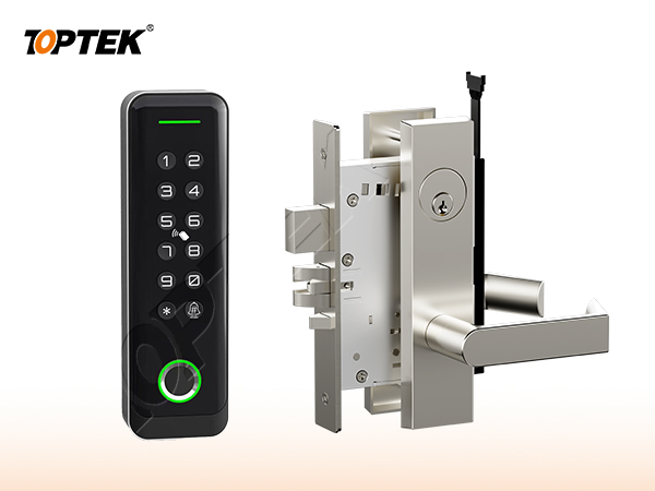
Electronic Lock and Access Control is only one part of the opening. The door leaf, frame, strike or rod interfaces, trim, cylinder, closer, power components where applicable, and the installation conditions all influence the result. Review the TKAMMRR9200(RR) motorized reference and TKAMSEC9200(EC) solenoid reference, then obtain the exact model wiring and connector data. A catalogue family name cannot replace a coordinated opening schedule.
Give every opening a unique number. Attach the current elevation, door and frame construction, thickness, swing, handing, hardware interfaces, finish, evidence requirements and sample reference. When one field changes, reopen the affected checks instead of assuming that the earlier approval remains equivalent.
Use a state-based approval test
Write the normal, locked, authorised-entry, emergency-egress, override and abnormal states that apply. For each state, record what the user does and what each latch, bolt, rod, lever, key or electrical input must do. Mark a state N/A when it truly does not apply; a blank field hides a decision.
Operate the labelled sample in the same sequence. Review from both sides of the door, then repeat the critical checks in representative preparation. Photograph labels and interfaces, but preserve the signed state table as the controlling approval record. Appearance alone cannot prove function.
Separate product evidence from project approval
A certificate, test report or declaration applies only to the product, construction, standard and configuration named in its scope. A project still needs to determine whether that evidence is the document it requires. Request current original records and compare model identifiers with the quotation, drawing and sample.
Do not turn an internal development test, a website badge, a similar model or a customer statement into third-party certification. If evidence remains open, record the missing document, responsible reviewer and due date. This draft intentionally avoids unsupported cycle, load, corrosion, fire or material claims.
Buyer approval checklist
- Opening number, door type, frame and swing
- Plain-language operating sequence from both sides
- Exact product, trim and interface references
- Door preparation and installation tolerances
- Required model-specific evidence and revision
- Labelled sample and acceptance owner
- Packaging, site inspection and handover controls
- Repeat-order change-control reference
Common mistakes and project risks
Typical errors include copying voltage or pinouts from a related model, selecting a transfer before counting monitoring conductors, measuring voltage only with no load, confusing controller output with physical lock state, and hiding unlabelled splices in a moving door. These gaps can produce intermittent actuation, misleading status, damaged components or difficult service calls.
The practical consequences can include re-machining, replacement hardware, revised wiring or keying, delayed inspection and uncontrolled site modification. Stop approval when the operating sequence, physical interface or evidence scope is unclear. A question recorded before production costs less than an assumption discovered across installed doors.
TOPTEK evidence and product scope
TOPTEK uses product-family material, model images and internal engineering observations to frame the buyer questions in this guide. These sources support a configuration discussion; they do not make every option, dimension or approval universal. The supplied configuration still has to be identified on a current drawing.
Use the TOPTEK resources centre for product documents and the applicable evidence request. Where a source describes internal testing, treat it as internal verification unless an original third-party document for the quoted configuration is separately reviewed.
RFQ checklist
- Opening number and point-to-point wiring diagram
- Exact lock model, actuator, fail-state and current wiring revision
- Voltage, current, duty, polarity and loaded-voltage acceptance basis
- Cable route, length, conductor size and connection count
- Door power-transfer type, preparation and conductor capacity
- Connector pinout, labels, spare conductors and monitoring point list
- Required evidence list and market/project basis
- Sample quantity, acceptance tests and owner
- Drawing, quotation and order revision control
- Production labels and packaging requirement
Why TOPTEK: turn selection into a controlled record
TOPTEK can review a marked-up schedule, translate shorthand into operating and interface questions, and identify missing information before quotation. The objective is not to guess the designer’s decision; it is to give the responsible parties a clear configuration to approve.
Quotation, drawing, sample label and order acknowledgement should carry the same reference. This lets door manufacturers, distributors, integrators and project teams detect substitutions or later changes. It also creates a practical basis for repeat-order inspection.
Two-level CTA
For an initial review, send the opening list, door images or elevations and the required user sequence. Highlight unknowns. TOPTEK can return a focused question list without presenting assumptions as confirmed facts.
For a formal RFQ, submit the approved schedule, drawings, interfaces, evidence requirements and sample protocol through the TOPTEK contact page. Request a configuration-specific response and identify the person authorised to approve deviations.
Conclusion
Good hardware selection is a controlled translation from user behaviour to product configuration. Define the function, verify the physical interfaces, check the applicable evidence and demonstrate the identified sample. Do not let a general product name carry decisions it cannot contain.
Preserve the result through procurement, production, installation and handover. That discipline reduces avoidable replacement risk while keeping every TOPTEK statement inside the evidence and configuration actually reviewed.
Frequently asked questions
Can one wiring diagram be used for every electronic mortise lock?
No. Use current model-specific voltage, current, duty, polarity, contact and connector information for the exact configuration.
Why measure voltage at the lock under load?
Cable and connection losses appear when current flows. An unloaded reading may not reveal the voltage available during actual actuation.
How many conductors does a door power transfer need?
Count the exact actuator and monitoring circuits from the approved point list, including commons, supervision and any approved spare policy.
Can wire colour be used as the connector pinout?
Colour can support identification, but the approved pin number, signal name and physical function should control the connection.
What should be tested at commissioning?
Test authorised entry, locking, inside egress, every monitoring point, loaded voltage, full door movement, power loss and mechanical override where applicable.