
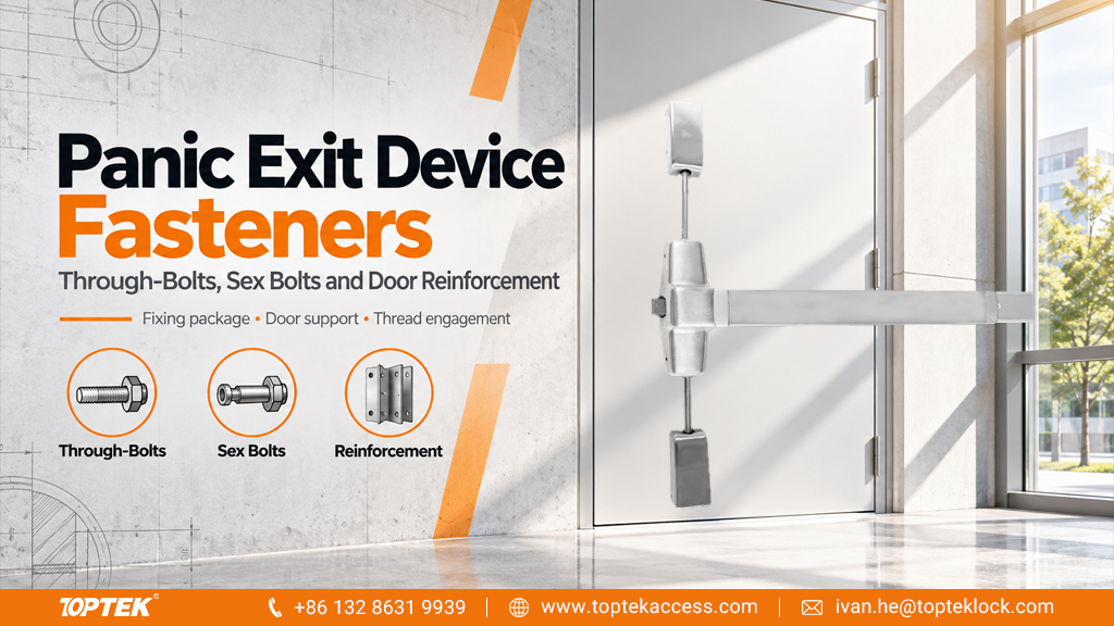

TL;DR: specify the fixing package with the exit device
- Identify the exact device, outside trim and door construction before choosing panic exit device fasteners.
- Machine screws, wood screws and through-bolts need different supporting structures. A matching screw head does not establish compatibility.
- Check door thickness, reinforcement position, thread engagement and clearance behind the device as one assembly.
- Keep the approved fixing schedule with the installation drawing and replacement-parts record.
Quick answer: which panic exit device fasteners should you use?
Use the fastener type and size specified for the exact exit device, outside trim and door construction. A reinforced metal door may provide a threaded fixing point; a suitable timber door may provide an approved blocking area; another assembly may require a through-bolt or sex-bolt arrangement. These are alternative installation details, not interchangeable upgrades. Confirm the complete stack thickness, supporting material, hole pattern and allowable hardware before ordering. If the door construction or fixing condition is unknown, ask the door and hardware suppliers to agree a documented detail before drilling or replacing fasteners.
This guide is for door manufacturers, distributors and project buyers preparing a fixing schedule. It addresses what must accompany the device order, how to distinguish common fixing arrangements and how to prevent substitutions that change the assembly.
Understand screws, through-bolts and sex bolts
A machine screw engages a compatible threaded component, such as an approved reinforcement or mating fastener. A wood screw relies on suitable timber support and the specified pilot preparation. A through-bolt passes through the assembly and engages an approved receiving component on the other side. A sex bolt is a mating arrangement with an internally threaded barrel and a matching screw; the barrel is sometimes described as a binding post.
Terminology varies between catalogues. Request a drawing or part reference whenever a purchase line says only “through fixing.” Confirm whether the supplier means a barrel-and-screw set, a bolt passing into the outside trim, or another specific arrangement. Those alternatives can require different preparation and can leave different hardware visible on the outside face.
| Fixing arrangement | What provides support | Information needed for an order |
|---|---|---|
| Machine screw into reinforcement | The specified threaded reinforcement behind the door face | Thread, reinforcement thickness, hole location and approved screw length |
| Wood screw into blocking | A suitable blocking zone in the timber door construction | Door construction, blocking location, screw specification and pilot preparation |
| Through-bolt into outside trim | The documented device-to-trim assembly | Trim reference, door thickness and the complete fixing stack |
| Sex-bolt assembly | A matched barrel and screw spanning the specified assembly | Barrel dimensions, mating thread, grip range and permitted head arrangement |
Verify the door support before selecting the screw
The visible door skin does not describe the whole fixing structure. For a metal door, obtain the reinforcement detail and confirm that its position matches the exit-device template. For a timber door, establish whether a suitable blocking area exists at every required location. Do not assume that the latch-end support also extends beneath the rear mounting bracket.
Allegion’s explanation of special laminated material blocking illustrates why this matters: the blocking supplies material for wood-screw mounting in a wood door. It is a useful example of the relationship between door construction and fastening, not approval to apply that detail to a different manufacturer’s door.
Ask the door supplier to identify the reinforcement or blocking on a section drawing. Include the device centreline and mounting-hole references so the two drawings can be compared. If the support is absent or damaged, selecting a thicker screw by eye does not establish a suitable repair. Obtain a repair or replacement detail from the responsible suppliers.
On a fire-rated opening, retain the applicable doorset evidence and installation instructions with the fixing detail. A fastener substitution or new through-hole needs assessment against that assembly’s documented limitations; the device family name alone does not establish permission.
Measure the complete fixing stack and thread engagement
Door thickness is only one dimension in a through-fixing arrangement. The mounting plate, device chassis, outside trim, permitted spacer and receiving component can all affect the length available for engagement. Use the supplier’s section drawing to identify the measurement reference points. A nominal door thickness copied from a schedule may differ from the thickness at the actual fixing position.
For each location, record the specified screw and mating component together. A screw that feels tight may have reached the bottom of a blind threaded hole before the device is clamped. Conversely, a screw that appears to fit may engage too little thread. Neither condition can be judged reliably from the visible head alone.
Do not apply a universal thread-engagement value for every panic device. The acceptable engagement, tightening method and any torque requirement come from the relevant assembly instructions. Confirm whether washers, sleeves or spacers are required, and avoid adding them simply to consume excess screw length.
Mixed metric and imperial hardware is another procurement risk. Similar diameters can conceal different thread pitches. Keep the manufacturer part number, thread specification and length in the purchase record. Separate approved alternatives from visually similar stock in the service store.
Coordinate the latch end, rear bracket, rods and outside trim
A rim device and a vertical-rod device do not have identical fixing packages. The latter can add rod guides and upper or lower latch assemblies, each with its own receiving structure. Start with the correct device drawing rather than multiplying the quantity from a similar-looking installation.
Outside trim can also change the fastener arrangement. Confirm whether trim and device share fixing points, how the mating parts engage and whether all fasteners remain accessible for authorised service. Check clearance to the cylinder, spindle, moving mechanism and any electrical option using the actual configuration drawing.
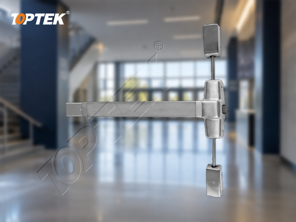
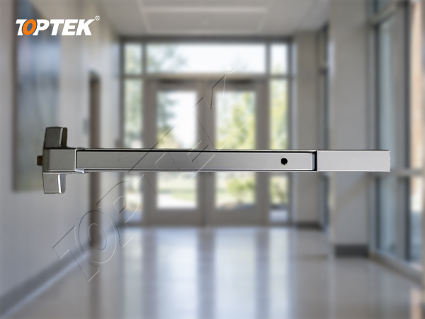
The TOPTEK panic exit device product page provides a starting point for model identification. Send the complete configuration with your enquiry; a product photograph does not show the internal reinforcement, exact thread or every installation accessory.
Inspect delivered fixing packs before door assembly
Receiving inspection should compare the pack with the agreed bill of materials, not simply count loose screws. Check labels, quantities, matched screw-and-barrel pairs, lengths and visible damage. Retain one approved reference pack with the corresponding device and trim references.
For a mixed-door order, keep packs separated by opening type. A thick door, a different trim or a different reinforcement can require a different fixing set even when the exit-device finish is identical. Clear packaging reduces the chance that installers choose the nearest available screw to complete a door.
Use an approved sample assembly to confirm that the device seats correctly and operates without interference after installation. Record the drawing revision, door construction and fixing references used. A successful fit on one sample does not automatically approve a changed substrate or a different trim on the production order.
Common fixing mistakes and project risks
- Reusing damaged threads: a screw entering an enlarged or stripped hole is not evidence of adequate support. Record the damage and obtain an authorised repair detail.
- Mixing unmatched barrels and screws: similar appearance can conceal differences in thread, length or head seating. Retain matched part references.
- Using extra tightening force: tightening cannot correct missing reinforcement or a wrong stack length. It can also distort unsupported parts.
- Ignoring the outside face: through-fixing affects the opposite face and its trim. Include that face in the drawing review.
- Applying one pack to every door: variations in thickness, material and trim need a deliberate compatibility check.
If an installed device moves on the door, the building operator should arrange qualified inspection promptly. Where reliable release or required latching is in doubt, manage the opening according to the site’s safety arrangements. The panic bar maintenance checklist supports recording the wider operating condition after the fixing issue is addressed.
Why TOPTEK: connect the product enquiry to the door drawing
Explore the TOPTEK panic exit device range with the door construction and outside-trim requirements available. Ask for the mounting drawing and fixing-pack information for the proposed configuration, then compare them with the door supplier’s reinforcement or blocking detail.
For distributors sourcing commercial door hardware, a useful order definition includes the device, trim, fasteners, accessories and documents together. Review the TOPTEK quality-management information alongside the model-specific records requested for the project. General manufacturing information does not replace evidence for a particular doorset or fixing arrangement.
RFQ checklist: request a fixing-package review
Send the following information for an initial configuration review:
- Device type, model reference, outside trim and installed options.
- Door material, measured thickness and reinforcement or blocking drawings.
- Mounting template, hole pattern and photographs of both door faces.
- Required screw, barrel, spacer and accessory references, if already specified.
- Existing-hole condition for replacement work and any proposed repair detail.
- Destination market, applicable doorset evidence, quantities and packing requirements.
After the configuration is agreed, request a formal quotation that identifies the complete fixing package, drawing revision, sample requirements and documents to accompany supply. This gives purchasing and installation teams a common reference when checking substitutions.
Frequently asked questions
Are sex bolts required for every panic exit device?
No. The required fixing arrangement depends on the device, trim and door construction. Follow the exact assembly instructions and confirm the supporting structure before selecting a fixing set.
Can I use the screws from the old exit device?
Only if the responsible supplier confirms their specification, condition and suitability for the replacement assembly. Matching head appearance or hole location does not prove compatibility.
Does a longer screw provide a stronger fixing?
Not automatically. A longer screw may bottom out or interfere with another component. Use the specified length, thread and engagement for the complete fixing stack.
What should a door manufacturer provide for the fixing review?
Provide the door construction, actual thickness, reinforcement or blocking detail and mounting-hole locations, together with the device and outside-trim references.
What should happen if a mounting hole is stripped?
Record the damage and obtain an authorised repair or replacement detail. Do not assume that a larger screw or additional tightening restores the original assembly.
Conclusion: order the support and fastener details together
The right panic exit device fasteners are the ones documented for the complete assembly. Confirm the receiving structure, stack thickness and mating parts before supply, then retain those references through installation and maintenance. A precise fixing package helps the project team avoid improvised substitutions and makes later service enquiries easier to resolve.