
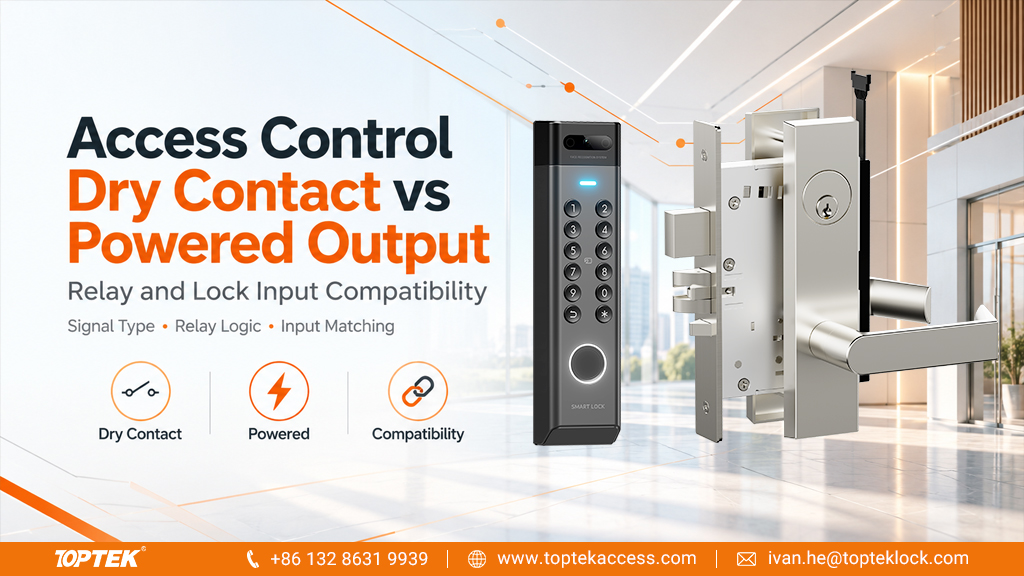

TL;DR: select the interface before selecting the connection
- A dry relay contact switches a circuit; it does not provide its own lock supply.
- A powered output delivers an electrical supply or signal within its specified limits. Confirm exactly which function the terminal performs.
- NO, NC and COM identify relay connections, not a complete door operating strategy.
- Check the lock input, controller configuration, power budget and required door behaviour together before approving a wiring diagram.
Quick answer: access control dry contact vs powered output
The difference between an access control dry contact and a powered output is what the output provides at the connection. A dry contact provides an electrically operated switching path without an internally supplied voltage at that path. A powered output supplies a specified voltage or electrical signal. Either may participate in a door release circuit, but they are not automatically interchangeable. First establish whether the lock expects switched supply power or a separate control signal. Then match the controller output type, ratings, configuration and reference connections to that exact requirement.
Read the terminal function, not just the word relay
A controller can contain a relay and still present a powered connection when a jumper or internal arrangement connects a supply to the relay common. Conversely, an isolated relay may switch an external supply that comes from another device. The presence of a relay symbol alone does not settle where the voltage originates. A procurement specification should identify the actual terminal configuration that will be delivered and commissioned.
A dry contact is sometimes called a potential-free or volt-free contact. Those descriptions concern the contact’s relationship to the device’s internal supply. They do not mean that an installed circuit can be touched or connected without electrical precautions. Once an external circuit is connected, voltage may be present across the terminals or relative to other equipment. Qualified installers should follow the documented isolation and verification procedure before changing wiring.
A useful manufacturer example is the AXIS A1210 user manual. Its relay and jumper descriptions distinguish isolated contacts from configurations that connect an internal supply to the relay common. This demonstrates why configuration matters. It is an example for that controller, not an instruction to reproduce its jumper arrangement or ratings on TOPTEK hardware.
Separate a lock power circuit from a release signal
| Connection being specified | What it does | What must be confirmed |
|---|---|---|
| Switched lock supply | Connects or interrupts the approved supply path | Supply characteristics, load demand, switching rating and required operating sequence |
| Dedicated release input | Requests a function while the lock may retain a separate supply | Whether the input expects a contact closure, voltage signal or another interface |
| Status output | Reports a supported physical or electrical condition | Output type, reference state and receiving input requirements |
| Auxiliary electronic output | Switches or signals according to its circuit design | Whether it is isolated, open-drain or another type, and its permitted load |
A motorized lock, for example, may have a power input and a separate command input. That arrangement cannot be assumed from the word motorized, nor can it be assumed that every release command is a dry closure. Obtain the terminal schedule for the chosen lock version. Applying supply voltage to an input designed only for a contact can damage equipment; using a contact where a powered signal is required may produce no response.
Likewise, a lock status contact is not a spare power output. Keep command and feedback connections distinct on the drawing. Use names that explain the function, such as release request or door position, and retain the manufacturer’s terminal identifiers beside them. This makes it easier to follow the same circuit across the controller drawing, door schedule and commissioning record.
Interpret NO, NC and COM in the correct reference state
For a conventional changeover relay, NO means normally open, NC means normally closed and COM means common. The normal state generally refers to the relay coil being de-energized, as defined in the device documentation. It does not automatically describe a locked door, an authorized entry condition or the controller’s powered standby state.
COM is not a universal synonym for ground or the negative supply connection. It is the common switching terminal of the relay contact arrangement. Connecting it to a supply reference without checking the drawing can create an unintended circuit. A signal ground, supply return and relay common may have different roles and should not be merged merely because their labels look familiar.
Write a small state table before choosing NO or NC. Include the controller’s normal operation, an authorized release command, loss of controller power, loss of lock supply and restoration. Record the expected relay state separately from the expected lock and door behaviour. The complete system determines those outcomes; selecting one contact label does not establish compliance or emergency operation.
Check switching ratings and available power separately
A relay contact rating describes an allowable switching duty under specified conditions. It does not mean the controller can supply that amount of power. The supply and controller may have a different total output budget, shared across several terminals and connected devices. Review both limits and the conditions attached to each rather than quoting the largest number in the datasheet.
Use the documented load profile for the selected lock. A steady running value may not cover starting demand or other operating phases. Confirm the relevant voltage type, permitted range, current demand, switching characteristics and duty. If several locks share a supply, evaluate the intended simultaneous operation and the other devices drawing from that source.
Cable losses and the voltage available at the door remain relevant when the output type is correct. The electronic mortise lock wiring guide addresses the broader wiring review. Keep that calculation separate from the dry-contact decision: an isolated contact does not compensate for an unsuitable supply, cable run or connector.
Protection for an inductive load also requires the actual manufacturer’s instructions. A diode, suppressor or other component must suit the circuit, polarity where applicable and required operation. Do not add a generic protection part across an unidentified motorized assembly or copy a diagram from a different output design.
Use a compatibility decision table before approving the diagram
| Proposed combination | Decision required | Approval evidence |
|---|---|---|
| Dry relay to a contact-operated command input | Confirm permitted contact behaviour and separation from the power circuit | Lock input instructions and controller relay configuration |
| Dry relay switching an external lock supply | Confirm switching suitability, supply selection and circuit protection | Load data and a reviewed connection diagram |
| Powered output to a lock power input | Confirm electrical compatibility and available supply capacity | Both datasheets and the complete power budget |
| Powered output to a contact-only input | Do not connect directly; obtain an approved interface design | Documented isolation or conversion arrangement if required |
| Open-drain output treated as a dry relay | Check the electronic output circuit and its reference requirements | Manufacturer instructions for that exact output |
Open-drain or transistor outputs deserve particular attention because they can look like a simple on/off switch in software. They are not automatically isolated contacts and may depend on an external pull-up, reference connection or load arrangement. Treat the electrical diagram as controlling evidence. A successful bench response in one improvised setup does not establish compatibility with the intended installation.
Commission the command, feedback and restoration as separate results
Begin with a reviewed drawing and confirmed component identities. The commissioning record should state the controller model and configuration, lock model and function, supply reference and drawing revision. Check connections and settings using the manufacturers’ prescribed procedures before applying power. Avoid experiments that combine two unidentified powered outputs or connect an energized supply to a contact-only input.
Test the authorized release request and observe the intended lock response. Then verify the separate status signals used by the system. A relay changing state does not prove that the lock completed its movement, and a closed door signal does not prove that a locking element engaged. Define each acceptance result in terms of the condition actually measured.
Include the approved power-loss and recovery scenarios in the test plan, coordinated with the building’s operating requirements. Record any unexpected retained command, restart delay or missing feedback and investigate before handover. Emergency release and escape provisions require their own applicable design and acceptance evidence; this interface comparison cannot replace that review.
Specify TOPTEK enquiries around the exact configuration
The TOPTEK electronic lock and access control range provides a starting point for product selection. For a specific enquiry, identify the proposed TKAMMRR9200RR product configuration and request its applicable interface information. Do not treat a product-family description as a pin assignment or a promise of compatibility with every controller.
For repeat orders, connect the accepted drawing and sample configuration to the purchase specification. The TOPTEK quality management information can support that documentation discussion, while model-specific evidence must identify the product and scope concerned. A general quality page does not certify an assembled access-control system.
- Provide the opening schedule, quantities and intended operating function.
- Identify the controller output type and its actual jumper or configuration state.
- Supply the lock input description, power source and complete load budget.
- Mark the command, feedback and reference connections on the drawing.
- State the required power-loss, restoration and emergency operating outcomes.
- Request the applicable documents, sample configuration and acceptance record.
Frequently asked questions
Does a dry contact mean there is no voltage on the installed wires?
No. A dry contact does not supply its own voltage to the switched circuit, but an external source can place voltage on the connected wires. Follow the equipment isolation and verification procedures before working on the circuit.
Can a dry relay contact power a door lock by itself?
No. It can switch a suitably designed external supply circuit within its permitted rating. The lock still needs an appropriate power source and an approved connection arrangement.
Is COM the same as ground?
No. COM identifies the common terminal in the relay switching arrangement. Its connection depends on the circuit diagram; it should not be treated as a universal ground or negative supply terminal.
Does choosing NC automatically make the whole door fail safe?
No. The lock function, wiring, controller behaviour, power sources and required emergency provisions determine the complete response. Verify the specified operating states for the assembled opening.
Can an open-drain output replace a dry relay contact?
Only where the receiving circuit and manufacturer instructions support that arrangement. An open-drain output is an electronic switching interface and is not automatically an isolated, potential-free contact.
Request an interface review or a configuration quotation
For an initial selection discussion, send the lock reference, controller terminal description and a simple connection sketch. Identify whether the question concerns switched power, a release command or a monitoring signal so the review addresses the correct interface.
For a formal quotation, add quantities, the approved operating sequence, document requirements and sample acceptance criteria. Discuss the complete requirement through TOPTEK’s commercial locks and access control manufacturing capabilities. A clear interface schedule gives purchasing, installation and commissioning teams the same technical reference.