

TL;DR
- Define the EN 14846 electromechanical mortise lock interface by exact lock version, control input, available outputs and mechanical exit function.
- Keep mechanical lock evidence, electromechanical evidence and escape-device or doorset evidence linked to their respective products.
- Separate a release command from measured latch, bolt, lever and door-position states.
- Approve the lock, strike, cylinder, lever, controller and power path as a coordinated arrangement before ordering production quantities.
Quick Answer
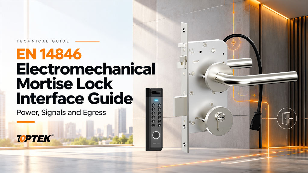
An EN 14846 electromechanical mortise lock interface review connects the European lock mechanism to power, control and monitoring while preserving the required mechanical operation. Identify the exact lock and strike, then record the input type, electrical limits, output meanings, cylinder action and inside exit sequence. The standard name does not provide a universal pinout or prove that a particular lock, reader and escape device are approved together. For commercial lock and access-control procurement, obtain the model-specific documents and demonstrate the complete arrangement against the project’s agreed functional and evidence requirements.
Understand the standards boundary before choosing a lock
The BSI entry for BS EN 14846:2008 identifies requirements and test methods for electromechanically operated locks and striking plates. It is a useful reference for defining the product evidence to request. It does not identify the configuration supplied for your door or replace the installation information for that configuration.
Mechanical locking, powered control and escape operation need separate attention. A mechanical EN 12209 lock document cannot simply be relabelled as evidence for an electromechanical assembly. Likewise, an electromechanical lock document does not automatically establish suitability of every cylinder, handle, strike or escape-device combination. Match the product identifiers and intended use across the documents.
Use the TOPTEK European mortise lock range to establish the mechanical family and required door function. Then identify the powered version and its supporting information. For a project requiring escape or fire performance, the responsible designer must also confirm the applicable hardware combination and doorset evidence.
Identify the mechanism and its physical interfaces
TOPTEK’s European powered range includes motorized and solenoid-controlled self-locking families. The TKEUS3592 solenoid-controlled self-locking mortise lock is one product reference for a configuration discussion. Other product identifiers describe different case or latch arrangements; they should not be treated as interchangeable electrical assemblies.
Begin with the backset, centres, forend, case envelope and strike. Add the follower arrangement, spindle engagement, cylinder profile and cam requirements. Confirm handing using an agreed drawing that identifies the inside and controlled outside. A reversible mechanical feature does not mean every operating sequence can be changed without following the version-specific instructions.
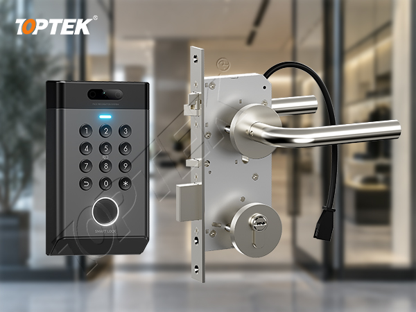
With a self-locking mechanism, establish how the lock recognizes the closing condition and when the bolt may project. Obtain the approved trigger and strike arrangement. A sample that operates on a desk does not establish correct timing when a real leaf approaches the frame under closer and seal forces.
Specify power and release commands without assumptions
The electrical schedule should identify supply type and permitted range, operating demand, any holding demand, polarity, protection and connection details. Use values from the selected version’s documentation. A family-level voltage description is not enough to select a power supply, controller output or cable for a particular opening.
Next define the release input. Is the lock expecting a documented contact action, a powered signal or communication through a specified device? Does the command enable a lever or move a locking element? Must it remain present during entry, or does an internal sequence finish the operation? These questions determine how the integrator configures the controller.
Keep the command path distinct from the power path. A controller contact may switch a separate supply; another arrangement may require an approved interface module. Connecting components because their terminal labels look similar can damage equipment or produce unpredictable operation. Ask both suppliers to confirm the same connection drawing.
Record abnormal electrical conditions
Describe loss of the lock supply, loss of a control connection and return of power as separate conditions. Identify any backup supply and what it continues to support. Establish the physical state of the outside lever and locking elements in each case, together with the required inside operation. Do not equate a stopped reader with a de-energized lock.
Build a signal dictionary that operators can trust
A monitoring output is useful only when its meaning is explicit. TOPTEK’s self-locking product information describes monitoring possibilities, but the order must specify which outputs the selected version actually provides. Require a connector reference, signal source, electrical type and state definition for every supplied output.
| Event or condition | Question for the supplier | Interpretation limit |
|---|---|---|
| Release command | Which input requests release and how is it applied? | A command does not prove mechanical release |
| Latch position | What movement does the sensor detect? | Do not infer door closure from latch movement alone |
| Deadbolt position | Which position changes the output? | Projection alone may not establish correct strike engagement |
| Lever operation | Which side and what movement are monitored? | Lever movement does not prove a completed exit |
| Cylinder action | Which key action or position is represented? | Do not assign key-holder identity from a mechanical contact |
| Door position | Is the sensor separate, and where is it mounted? | Door closure and lock engagement remain different conditions |
Agree how the controller interprets the normal, active and fault conditions. Where contacts are used, define their state against a stated mechanical condition instead of relying on “normally open” without context. Test the displayed event while observing the actual hardware. The lock monitoring guide provides a broader method for keeping signals and physical states distinct.
Preserve mechanical exit and cylinder operation
Write the required inside-lever action with the door latched, with any applicable bolt projected, and under the specified power conditions. If the project requires a particular escape-device arrangement, obtain its documented compatible lock and operating hardware. A general description such as “escape function” cannot replace that combination review.
The cylinder has a separate role. Confirm its profile, cam, dimensions and interaction with the powered mechanism. Demonstrate the intended outside override with the selected trim fitted. Establish whether key operation changes a maintained setting or only retracts a locking element for one entry. Record the state after removing the key.
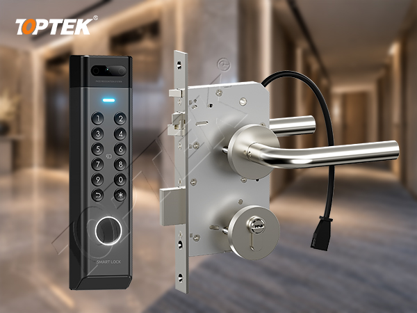
Do not transfer instructions between a conventional latch and a cross-latch arrangement without checking the receiving geometry and installation requirements. Their external appearance helps identify the discussion, but the current drawing determines preparation. Confirm cable clearance behind the case before drilling and keep fasteners clear of the intended wiring route.
Check evidence and sample results as separate records
Ask for the exact model, variant and document revision covered by any declared performance or certificate. Read the scope, issuing organization and applicable limitations. If the proposed cylinder, strike or powered option differs from the evidenced configuration, ask how the change is covered. Avoid treating a document for the mechanical family as evidence for every powered version.
TOPTEK’s electronic engineering capability supports discussion of actuation and integration. Engineering capability, an internal sample test and third-party product evidence answer different questions. Keep their records separate so the buyer can see what supports the design and what supports a formal performance claim.
For sample acceptance, identify the lock, strike, trim, cylinder, controller and supply. Record drawing revisions and the operating sequence used. Demonstrate authorized entry, relatching, inside operation, override, supplied monitoring and relevant fault recovery. A successful test applies to the tested arrangement; carry its identifiers into procurement and installation.
Common mistakes and project risks
- Using EN 14846 as a substitute for a model-specific electrical schedule.
- Describing every signal as “lock status” and leaving the controller programmer to guess.
- Assuming a self-locking bolt proves the door has reached its correct closed position.
- Changing the strike or cylinder after the sample without reviewing mechanical and evidence compatibility.
These shortcuts can create nuisance alarms, intermittent entry failures or a lock that operates differently from the approved sequence. The practical remedy is a shared interface record: one lock identifier, one preparation drawing, one signal dictionary and one accepted operating sequence for each configuration.
Resolve conflicts before releasing a production order. If the desired security condition contradicts the required exit or emergency behaviour, refer the opening to the responsible project designer. Neither the installer nor the supplier should infer the intended building strategy from a short hardware description.
Why TOPTEK and how to prepare the RFQ
TOPTEK provides European mechanical lock families alongside motorized and solenoid development options. Buyers can therefore coordinate the lockcase, lever and cylinder questions with the powered interface. The product scope must still identify the actual model and documented options; it should not imply that every family member shares the same signals or approvals.
For an initial review, send the door profile, inside and outside operating requirements, and proposed controller interface through TOPTEK’s commercial lock and access-control manufacturing page. Request the appropriate configuration drawing and a list of evidence needed for the proposed opening.
Request a documented lock and interface quotation
- Provide model or platform, latch type, self-locking requirement and door quantities.
- Include backset, centres, forend, strike, handing, follower, trim and cylinder details.
- Attach the supply specification, command sequence and required monitoring signals.
- State power-loss, recovery, override and inside-exit requirements.
- List the required evidence, sample tests, documentation language and revision owner.
The strongest interface specification lets an engineer trace each required user action to a mechanical component, electrical input and observable result. Keep that traceability through sample review, installation and maintenance. It turns a broad standards reference into a controlled purchasing decision.
Frequently asked questions
Does EN 14846 provide a universal wiring diagram?
No. Wiring, electrical ratings and control behaviour must come from the documents for the exact lock or strike configuration.
Can EN 12209 documents cover every powered variant?
No. Match each document to the product and performance it actually covers, and obtain the applicable evidence for the selected electromechanical version.
Is a bolt-position signal the same as a door-position signal?
No. They describe different physical conditions and may use different sensors. Define and test each signal separately.
Does an escape-function description approve every lever and cylinder?
No. Confirm the documented hardware combination, mechanical operation and applicable opening requirements for the selected arrangement.
What is the minimum useful first enquiry?
Send the door profile, required inside and outside actions, proposed controller interface and evidence requirements so TOPTEK can identify the next configuration checks.