

TL;DR
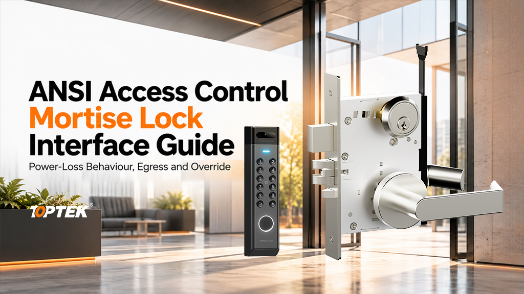
- Define the ANSI access control mortise lock interface around the complete lockset: case, trim, cylinder, strike and electrical control.
- Write separate requirements for outside entry, inside egress and mechanical override before choosing a power-loss mode.
- Distinguish motorized actuation from solenoid control; neither name establishes a wiring diagram or electrical rating.
- Approve the selected function and connected components together, then preserve their part numbers and revisions for repeat orders.
Quick Answer
An ANSI access control mortise lock interface is the set of mechanical and electrical connections that allows a specified lockset to operate with a door controller. Start with outside-lever behaviour, inside operation, cylinder action and latch or deadbolt movement. Then define power, release commands, monitoring and behaviour when power disappears or returns. A commercial door lock can retain secure outside access while providing the specified mechanical exit function. Its grade, appearance or reader brand does not establish that combination. Confirm it through the exact lock configuration, interface drawing and an installed sample.
Start with the ANSI lockset function
The first decision is what the user can do on each side of the opening. A credential may temporarily enable an outside lever, release a locking element or initiate motor-driven movement. These are different operations. Describe the required result in ordinary language before attaching a function code or product name to it.
For example, specify whether the outside lever remains inactive between authorized entries and whether a key retracts the latch directly or changes a maintained lever state. Record what happens when the key is removed. On the inside, describe the required operation with the latch engaged and, where fitted, with the deadbolt projected. This avoids approving a reader demonstration while overlooking the mechanical function.
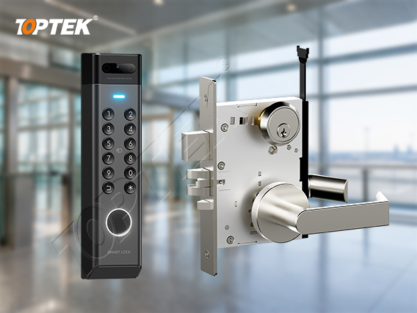
The TOPTEK ANSI mortise lock range provides the mechanical platform context. Electrification adds another selection layer. A mechanical function designation alone does not identify a motor, solenoid, connector, monitoring package or power-loss configuration.
Choose the actuation method and define its boundary
TOPTEK’s product range distinguishes motorized ANSI mortise locks from solenoid-controlled models. The TKAMMRR9200RR motorized mortise lock is a concrete starting point for motorized applications. The solenoid family includes TKAMSRR9200RR and TKAMSEC9200EC. Selection still requires the applicable function and electrical specification.
A motorized mechanism uses a motor to drive an action. A solenoid-controlled arrangement uses electromagnetic actuation to change a controlled condition. Do not assume that either description tells you which bolt retracts, whether a lever becomes active, or how long the system must maintain a command. Ask for a sequence diagram tied to the proposed version.
| Interface decision | Information to obtain | Procurement consequence |
|---|---|---|
| Controlled component | Lever coupling, latch, deadbolt or another identified mechanism | The release command must produce the required user action |
| Power supply | Supply type, operating range, peak and holding demand where applicable | Size the supply and transmission path from model data |
| Command input | Documented contact, powered input or communication interface | Confirm compatibility with the selected controller output |
| State feedback | Each supplied output, its meaning and electrical limits | Map the actual signal to a useful controller event |
| Mechanical override | Cylinder format, cam and resulting lock state | Retain usable access under the specified fault conditions |
A quotation that only says “access control compatible” leaves these decisions unresolved. Ask the supplier to identify the lock-side boundary and ask the integrator to identify the controller-side boundary. Their drawings should meet at the same connector or terminal reference.
Separate power-loss behaviour from inside egress
Fail-safe and fail-secure normally describe the controlled access side when electrical power is removed. They do not, by themselves, describe every inside-lever action. Specify outside security and inside operation separately, including any deadbolt interaction. The responsible project designer must resolve the required behaviour for the opening and its applicable rules.
Power loss also needs a location. A failed lock supply, a disconnected door cable and a controller fault can produce different conditions. A controller can stop communicating while the lock remains powered. A backup supply can keep a lock energized after the mains fails. State the relevant fault and the expected physical response, rather than writing one ambiguous “power off” row.
Include recovery. After power returns, define whether the door resumes its normal access schedule, completes an interrupted movement or requires a separate authorized command. Demonstrate the selected behaviour without assuming that one model’s recovery logic applies to another. The power-loss selection guide explains the wider system questions; the ANSI lockset schedule must identify their specific mechanical consequences.
A useful acceptance sequence
Record the initial door and lock state, apply one defined input, observe both sides, and compare the result with the approved sequence. Repeat with the relevant power and controller conditions. For an occupied escape route, arrange safe testing with the responsible site team; never leave required exit operation dependent on an informal test setup.
Coordinate trim, cylinder and strike before wiring approval
The electrical design cannot correct a mechanical mismatch. Confirm the rose or escutcheon fixing pattern, spindle arrangement, door thickness and cylinder projection. Check that screws and cable routes do not occupy the same space. A trim change can affect fastener length and the clearance available for the connector even when the lockcase stays the same.
For mechanical override, use the specified cylinder format and cam. Demonstrate the actual key action with the selected trim fitted. Check removal positions and the resulting outside-lever state. Include the keying authority in the handover plan so maintenance staff know who may use, replace or reorder override cylinders.
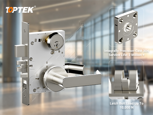
Inspect the strike and door alignment with the assembly fitted. The latch must meet the intended receiving geometry without binding, and any auxiliary mechanism must interact with the strike as designed. A bench sample can establish basic operation, but it cannot reproduce an incorrectly prepared frame or an overloaded door seal.
Request the connector designation, pin numbering, conductor purpose, polarity where relevant, shielding requirements and permitted cable arrangement. Use the specified actuation demand and route length to check supply performance at the lock. Do not substitute a holding-current figure for the demand during movement, and do not assume a controller relay can directly supply the lock.
Monitoring needs equally careful naming. “Door closed,” “latch engaged,” “bolt projected” and “inside lever operated” describe different conditions. Record the sensor that produces each signal and whether that sensor belongs to the lock or another door component. A release command indicates an instruction; it does not prove that a person entered or that the door subsequently secured.
Define the normal, active and fault states of each available output. Match the output type and rating to the controller input. Test the event names shown to the operator against real hardware movement. If the interface specification does not include a particular feedback signal, do not promise that the management system can derive it from another unrelated contact.
Review evidence and avoid common specification errors
The BHMA overview of ANSI/BHMA A156.13-2022 describes mechanical mortise-lock evaluation. BHMA also publishes a separate A156.25-2023 overview for electrified locking systems. Use the relevant requirements and model-specific documentation; a mechanical grade does not establish every electrical or system property.
TOPTEK’s electronic engineering information describes its development capability. Capability information supports an engineering discussion, while a certification or listing claim requires the applicable issued evidence and model scope. For fire-rated or escape-route openings, review the complete approved hardware and door arrangement with the responsible specialist.
- Do not copy electrical values from a visually similar lock.
- Do not treat a reader’s green light as proof of latch retraction.
- Do not use a mechanical override demonstration as a substitute for checking inside operation.
- Do not approve one cable assembly and fit another without reviewing pinout and ratings.
These errors can cause failed entry, misleading alarms, insecure relocking or costly changes after the door is machined. Assign ownership of the lock drawing, system sequence and installed acceptance record before issuing the purchase order.
Why TOPTEK and what to include in the RFQ
TOPTEK combines mechanical mortise-lock platforms with motorized and solenoid product development. This gives buyers a way to discuss the lockcase, trim and electronic interface together. The useful output is an identified configuration with documented boundaries, rather than a broad promise of compatibility with every access-control system.
Begin with the opening number and a short description of the entry and exit actions. If the project is still being defined, send a door-edge photograph, the proposed controller information and the required operating sequence through the TOPTEK commercial lock and access-control project team. Ask which drawings and sample checks are needed next.
Request a formal configuration quotation
- Identify the ANSI lock model, mechanical function, motor or solenoid version, and quantities by opening.
- Provide trim, spindle, cylinder, strike, handing and door-preparation references.
- Attach the power, command, monitoring and fault-recovery requirements.
- List the applicable evidence, project acceptance criteria and document revisions.
- State sample quantities, delivery stages, packaging and responsibility for installed commissioning.
Ask the quotation to separate confirmed specifications from options requiring a configuration choice. Retain the accepted sample and interface schedule as references for production and service replacements. A sound ANSI interface selection ends with a repeatable door function, not merely a connected reader.
Frequently asked questions
Does ANSI Grade 1 define the access-control wiring?
No. Obtain the wiring diagram and electrical ratings for the exact powered lock configuration; a mechanical grade does not provide a pinout.
Can fail-secure outside access coexist with mechanical inside exit?
It can in a suitable lock function. Specify and verify outside power-loss behaviour and inside operation separately for the approved opening.
Does a motorized lock use the same command as a solenoid lock?
Do not assume so. Confirm the input type, actuation sequence and electrical requirements for each selected version.
What must a cylinder override check establish?
It must establish compatible cylinder and cam geometry, the actual key action, key-removal positions and the resulting lock state with the selected trim installed.
What should remain in the handover record?
Keep the model and function references, current drawings, wiring and signal schedule, approved operating sequence, evidence list and installed acceptance results.