

Electronic Mortise Lock Power-Loss Guide: Fail-Safe, Fail-Secure and Monitoring
TL;DR
Fail-safe and fail-secure describe the intended state of a controlled lock function when power is removed. They do not by themselves define inside egress, fire-alarm response, mechanical override, deadbolt position, monitoring or overall security. Create a state table for normal power, authorised access, alarm input, backup operation and total power loss, then verify the exact quoted model.
Start with the Electronic Lock and Access Control product hub, then use this narrower guide to define the required function and approval evidence.
Quick Answer
Ask what each person and component can do with power on and power off. Keep outside access, inside exit, latch/deadbolt condition, key override and monitoring on separate rows. The system designer approves the required life-safety and security sequence; TOPTEK supplies configuration-specific data and an identified sample for verification.
Fail-safe and fail-secure answer a narrow question
In common access-control use, fail-safe means the electrically controlled function releases or unlocks when its power is removed, while fail-secure means that function remains secured. The exact result still depends on the mechanism and configuration. Do not extend the label to every lever, bolt, key or signal without model documentation.
The correct selection is a project design decision shaped by door location, security zoning, egress, fire strategy and local acceptance. A supplier should not choose the state from habit or a room name. The RFQ should quote the approved operating narrative and identify who has authority to resolve conflicts.
Describe inside egress independently
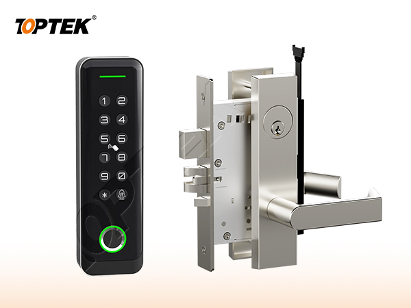
Inside egress can remain mechanically available even when an outside function is fail-secure, depending on the exact lock. Conversely, a fail-safe outside release label does not prove that every inside component meets the required egress arrangement. Write what the inside lever or operator does in each normal and abnormal state.
TOPTEK internal electronic-lock material describes inside escape and controlled outside access for certain solenoid families. Treat this as a family design direction to confirm on the quoted configuration. The applicable project documents and responsible reviewers must approve the complete opening.
Separate power source, backup and alarm commands
Loss of utility supply, failure of one power circuit, exhausted backup power and a deliberate fire-alarm release are different events. A controller or relay command can also change the lock while power remains available. Put these events on separate rows so the design does not confuse “power off” with “system commanded open”.
Confirm voltage, current, inrush where relevant, duty, polarity, cable distance, voltage drop, supply capacity and backup duration from current model and system information. TOPTEK material mentions a 12–24 V range for certain solenoid families, but the actual quoted model values must be checked rather than inferred.
Define mechanical override and key control
A cylinder or other mechanical override gives authorised users a path that is separate from the electronic command. State whether it retracts a latch, changes a lever state, operates a deadbolt or provides another model-specific result. Also define whether it works during total power loss.
The key hierarchy, cylinder format, length and drive interface must match the lock and organisational handover. An override that exists physically but is unavailable to responders or does not operate the expected function is not a complete emergency plan. Demonstrate it on the approved sample.
| State or interface | Define | Acceptance evidence |
|---|---|---|
| Normal power | Outside/inside operator and latch/bolt states | State-table demonstration |
| Authorised command | What input changes which controlled function | Controller and lock test |
| Alarm command | Required system response and responsible interface | Witnessed project test |
| Power loss | Fail-safe or fail-secure state plus inside egress | Unpowered sample/opening test |
| Mechanical override | Key action and resulting mechanism state | Identified key and sample |
| Monitoring | Contact type and physical meaning | Signal-to-physical-state comparison |
Monitoring reports state; it does not create it
Door-position, latch, deadbolt, lever, request-to-exit and tamper signals are different observations. A controller may show a command was sent while the physical door remains open or the latch has not engaged. Specify the required contact, its normal condition, cable conductors and controller interpretation.
Verify each signal against the real mechanism during commissioning. Record powered, unpowered and mechanically overridden states. Do not assume that a monitored model includes every contact or that a website family image proves a specific output. Request the current wiring information for the exact configuration.
Approve the opening as a system
Electronic Lock and Access Control is only one part of the opening. The door leaf, frame, strike or rod interfaces, trim, cylinder, closer, power components where applicable, and the installation conditions all influence the result. Use the TKAMSEC9200(EC) solenoid reference, TKAMMRR9200(RR) motorized reference and electronic product hub to begin a model-specific enquiry. A catalogue family name cannot replace a coordinated opening schedule.
Give every opening a unique number. Attach the current elevation, door and frame construction, thickness, swing, handing, hardware interfaces, finish, evidence requirements and sample reference. When one field changes, reopen the affected checks instead of assuming that the earlier approval remains equivalent.
Use a state-based approval test
Write the normal, locked, authorised-entry, emergency-egress, override and abnormal states that apply. For each state, record what the user does and what each latch, bolt, rod, lever, key or electrical input must do. Mark a state N/A when it truly does not apply; a blank field hides a decision.
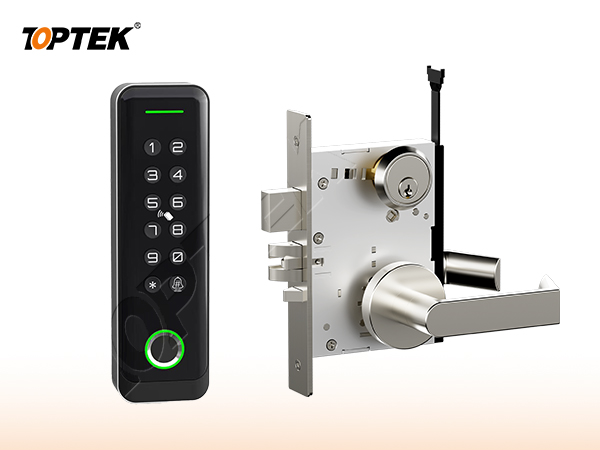
Operate the labelled sample in the same sequence. Review from both sides of the door, then repeat the critical checks in representative preparation. Photograph labels and interfaces, but preserve the signed state table as the controlling approval record. Appearance alone cannot prove function.
Separate product evidence from project approval
A certificate, test report or declaration applies only to the product, construction, standard and configuration named in its scope. A project still needs to determine whether that evidence is the document it requires. Request current original records and compare model identifiers with the quotation, drawing and sample.
Do not turn an internal development test, a website badge, a similar model or a customer statement into third-party certification. If evidence remains open, record the missing document, responsible reviewer and due date. This draft intentionally avoids unsupported cycle, load, corrosion, fire or material claims.
Buyer approval checklist
- Opening number, door type, frame and swing
- Plain-language operating sequence from both sides
- Exact product, trim and interface references
- Door preparation and installation tolerances
- Required model-specific evidence and revision
- Labelled sample and acceptance owner
- Packaging, site inspection and handover controls
- Repeat-order change-control reference
Common mistakes and project risks
Typical errors are choosing fail state from habit, treating alarm release as identical to supply failure, copying electrical values from another model, assuming inside egress from an outside fail-state label, and approving monitoring without comparing it to physical states. Another risk is omitting cable voltage drop, door power transfer or backup-power responsibility from the opening schedule.
The practical consequences can include re-machining, replacement hardware, revised wiring or keying, delayed inspection and uncontrolled site modification. Stop approval when the operating sequence, physical interface or evidence scope is unclear. A question recorded before production costs less than an assumption discovered across installed doors.
TOPTEK evidence and product scope
TOPTEK uses product-family material, model images and internal engineering observations to frame the buyer questions in this guide. These sources support a configuration discussion; they do not make every option, dimension or approval universal. The supplied configuration still has to be identified on a current drawing.
Use the TOPTEK resources centre for product documents and the applicable evidence request. Where a source describes internal testing, treat it as internal verification unless an original third-party document for the quoted configuration is separately reviewed.
RFQ checklist
- Approved normal, alarm, backup and total-power-loss state table
- Exact model, actuator and fail-state configuration
- Inside egress and outside access in every applicable state
- Mechanical override function, cylinder and key-control plan
- Voltage, current, duty, cable distance and supply/backup data
- Monitoring contacts, controller meanings and commissioning tests
- Required evidence list and market/project basis
- Sample quantity, acceptance tests and owner
- Drawing, quotation and order revision control
- Production labels and packaging requirement
Why TOPTEK: turn selection into a controlled record
TOPTEK can review a marked-up schedule, translate shorthand into operating and interface questions, and identify missing information before quotation. The objective is not to guess the designer’s decision; it is to give the responsible parties a clear configuration to approve.
Quotation, drawing, sample label and order acknowledgement should carry the same reference. This lets door manufacturers, distributors, integrators and project teams detect substitutions or later changes. It also creates a practical basis for repeat-order inspection.
Two-level CTA
For an initial review, send the opening list, door images or elevations and the required user sequence. Highlight unknowns. TOPTEK can return a focused question list without presenting assumptions as confirmed facts.
For a formal RFQ, submit the approved schedule, drawings, interfaces, evidence requirements and sample protocol through the TOPTEK contact page. Request a configuration-specific response and identify the person authorised to approve deviations.
Conclusion
Good hardware selection is a controlled translation from user behaviour to product configuration. Define the function, verify the physical interfaces, check the applicable evidence and demonstrate the identified sample. Do not let a general product name carry decisions it cannot contain.
Preserve the result through procurement, production, installation and handover. That discipline reduces avoidable replacement risk while keeping every TOPTEK statement inside the evidence and configuration actually reviewed.
Frequently asked questions
What is the difference between fail-safe and fail-secure?
Fail-safe releases the specified controlled function when power is removed, while fail-secure keeps that specified function secured; exact behaviour remains configuration-specific.
Does fail-secure mean people cannot exit during power loss?
Not necessarily. The outside controlled state and inside egress are separate requirements that must be defined and tested for the exact lock.
Is a fire-alarm release the same as loss of power?
No. An alarm command, controller action, supply failure and exhausted backup can be different system states and should be documented separately.
What electrical data should the RFQ include?
Include model-specific voltage, current, duty, polarity, cable distance, voltage drop, supply capacity, backup and controller interface information.
Which monitoring signals should be checked?
Check only the contacts required and available on the quoted configuration, such as door position, latch, deadbolt or request-to-exit, and verify each against the physical state.