

Multi Point Door Lock Replacement Guide: Measure Centres, Backset, Faceplate and Lock Points
TL;DR
A reliable multi point door lock replacement needs a full opening record, not one gearbox dimension. Measure centres, backset, central case, faceplate length and width, spindle and cylinder interfaces, every hook or bolt position, end cuts and keeps. Also document whether the mechanism is automatic, lift-to-lock or key-operated and what the door does in each state.
Start with the Multi-point Locking Systems product hub, then use this narrower guide to define the required function and approval evidence.
Quick Answer
Remove the existing mechanism only when authorised and safe. Photograph it in the door, mark a fixed datum, measure every point from that datum, record the operating sequence and compare the keeps. Send the full strip, door edge and schedule information with the RFQ; approve a matched sample before altering the door.
Start with identity and operation before dimensions
Record the door number, material, thickness, swing, handing and current symptoms. Then write how the existing system is supposed to lock: automatically when the door closes, after the handle is lifted, or through cylinder rotation. A replacement with similar dimensions but different operating logic can create an unsafe or unusable opening.
Test the existing mechanism only within the approved site procedure. Note what projects the locking points, what retracts them, whether the cylinder deadlocks the handle, and which inside and outside operators remain active. Distinguish a damaged lock from a door-alignment problem before using the failure as a model reference.
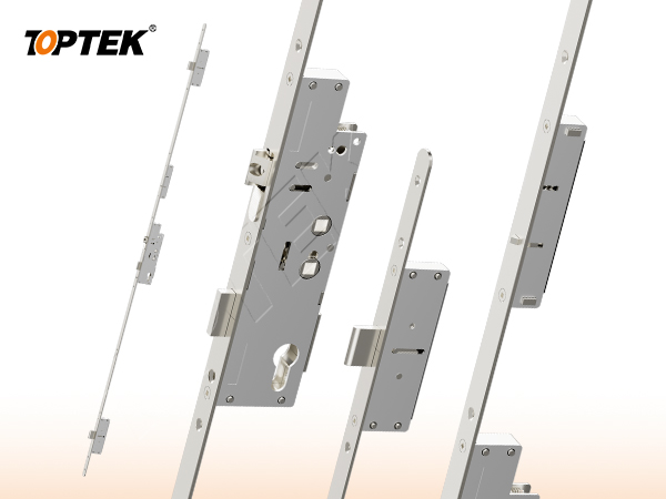
Use one fixed datum for every vertical measurement
Choose a reproducible datum such as the spindle centre or an identified faceplate end, then state it on the sketch. Measure the centre of every hook, roller, shoot bolt, latch and deadbolt from the same datum. Mixing measurements from the top for some points and from the spindle for others creates avoidable ordering errors.
Record whether each dimension is a centre line, overall edge or projection. Include top and bottom end cuts, extension pieces and any adjustable features. A photograph with a tape measure is useful evidence, but it does not replace a dimensioned drawing because perspective can distort the apparent positions.
Measure the central case and door interfaces
Centres describe the relationship between the lever spindle and cylinder or key centre. Backset runs from the faceplate or door edge datum to the spindle or lock reference centre. Also record central-case height, depth, thickness, spindle size, cylinder format and cam or drive relationship.
Do not assume that a shared centres or backset value makes two gearboxes interchangeable. Screw positions, case pockets, latch/deadbolt geometry, follower construction and drive logic may differ. Use actual dimensions from the existing lock and compare them with the current proposed drawing.
Measure the complete faceplate, not a convenient section
Record faceplate overall length, width, thickness, profile, end shape, joint positions and fixing-hole centres. TOPTEK internal engineering experience notes that long faceplates can bend during transport or installation; inspect flatness before treating a curved strip as the correct door-edge profile.
Also examine the door edge pocket. An old faceplate may have been forced into an uneven recess or locally modified. The replacement decision should not reproduce an uncontrolled site alteration. Mark existing damage, filler, corrosion or non-standard machining for the responsible door specialist.
| Measurement group | Record | Why it matters |
|---|---|---|
| Function | Automatic, lift-to-lock or key-operated | Prevents a logic mismatch |
| Central case | Centres, backset, depth, case and fixing dimensions | Controls the main door pocket and trim |
| Faceplate | Length, width, thickness, ends, joints and holes | Controls door-edge fit |
| Locking points | Type and centre position from one datum | Controls engagement with every keep |
| Interfaces | Spindle, cylinder, cam/drive and handles | Controls user operation |
| Frame | Keeps, gaps, seals and compression | Separates lock fit from opening alignment |
Map locking points to keeps and compression
Each hook, bolt or roller needs its corresponding frame keep recorded by height, type and engagement condition. Measure the lock and the frame separately. A correct new mechanism can still operate poorly when a sagging door, compressed gasket or displaced keep loads the locking points.
Before ordering, check gaps and compression with the door supported in its normal condition. Do not force a handle or key against resistance. Site teams should correct approved alignment causes and then confirm that the replacement sample projects and retracts every point without side load.
Approve the opening as a system
Multi-point Locking Systems is only one part of the opening. The door leaf, frame, strike or rod interfaces, trim, cylinder, closer, power components where applicable, and the installation conditions all influence the result. Compare the opening with the TOPTEK Auto Lock and PD1000 product-family pages, while relying on a current configuration drawing for actual dimensions and function. A catalogue family name cannot replace a coordinated opening schedule.
Give every opening a unique number. Attach the current elevation, door and frame construction, thickness, swing, handing, hardware interfaces, finish, evidence requirements and sample reference. When one field changes, reopen the affected checks instead of assuming that the earlier approval remains equivalent.
Use a state-based approval test
Write the normal, locked, authorised-entry, emergency-egress, override and abnormal states that apply. For each state, record what the user does and what each latch, bolt, rod, lever, key or electrical input must do. Mark a state N/A when it truly does not apply; a blank field hides a decision.
Operate the labelled sample in the same sequence. Review from both sides of the door, then repeat the critical checks in representative preparation. Photograph labels and interfaces, but preserve the signed state table as the controlling approval record. Appearance alone cannot prove function.
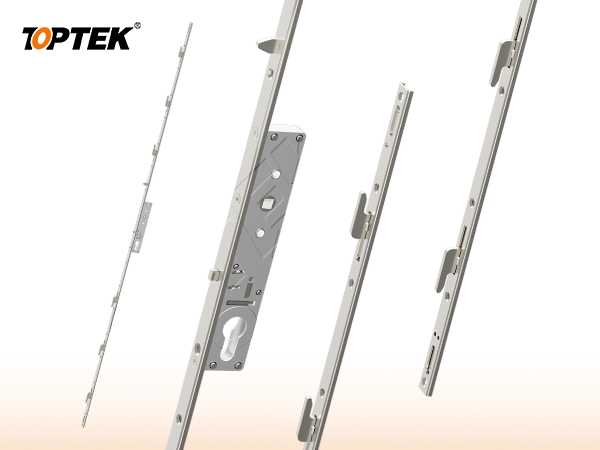
Separate product evidence from project approval
A certificate, test report or declaration applies only to the product, construction, standard and configuration named in its scope. A project still needs to determine whether that evidence is the document it requires. Request current original records and compare model identifiers with the quotation, drawing and sample.
Do not turn an internal development test, a website badge, a similar model or a customer statement into third-party certification. If evidence remains open, record the missing document, responsible reviewer and due date. This draft intentionally avoids unsupported cycle, load, corrosion, fire or material claims.
Buyer approval checklist
- Opening number, door type, frame and swing
- Plain-language operating sequence from both sides
- Exact product, trim and interface references
- Door preparation and installation tolerances
- Required model-specific evidence and revision
- Labelled sample and acceptance owner
- Packaging, site inspection and handover controls
- Repeat-order change-control reference
Common mistakes and project risks
Common replacement errors include measuring only centres and backset, ignoring operation type, assuming all three-point locks share the same point positions, copying dimensions from a distorted strip, and reusing misaligned keeps without inspection. Another risk is machining the door before the identified replacement sample has been compared with the approved drawing.
The practical consequences can include re-machining, replacement hardware, revised wiring or keying, delayed inspection and uncontrolled site modification. Stop approval when the operating sequence, physical interface or evidence scope is unclear. A question recorded before production costs less than an assumption discovered across installed doors.
TOPTEK evidence and product scope
TOPTEK uses product-family material, model images and internal engineering observations to frame the buyer questions in this guide. These sources support a configuration discussion; they do not make every option, dimension or approval universal. The supplied configuration still has to be identified on a current drawing.
Use the TOPTEK resources centre for product documents and the applicable evidence request. Where a source describes internal testing, treat it as internal verification unless an original third-party document for the quoted configuration is separately reviewed.
RFQ checklist
- Existing product markings and complete photographs
- Operating sequence and current symptom description
- Centres, backset, case depth and spindle/cylinder interfaces
- Faceplate length, width, thickness, ends and fixing holes
- Every locking-point type, height and projection requirement
- Keep positions, door gaps, seals and compression condition
- Required evidence list and market/project basis
- Sample quantity, acceptance tests and owner
- Drawing, quotation and order revision control
- Production labels and packaging requirement
Why TOPTEK: turn selection into a controlled record
TOPTEK can review a marked-up schedule, translate shorthand into operating and interface questions, and identify missing information before quotation. The objective is not to guess the designer’s decision; it is to give the responsible parties a clear configuration to approve.
Quotation, drawing, sample label and order acknowledgement should carry the same reference. This lets door manufacturers, distributors, integrators and project teams detect substitutions or later changes. It also creates a practical basis for repeat-order inspection.
Two-level CTA
For an initial review, send the opening list, door images or elevations and the required user sequence. Highlight unknowns. TOPTEK can return a focused question list without presenting assumptions as confirmed facts.
For a formal RFQ, submit the approved schedule, drawings, interfaces, evidence requirements and sample protocol through the TOPTEK contact page. Request a configuration-specific response and identify the person authorised to approve deviations.
Conclusion
Good hardware selection is a controlled translation from user behaviour to product configuration. Define the function, verify the physical interfaces, check the applicable evidence and demonstrate the identified sample. Do not let a general product name carry decisions it cannot contain.
Preserve the result through procurement, production, installation and handover. That discipline reduces avoidable replacement risk while keeping every TOPTEK statement inside the evidence and configuration actually reviewed.
Frequently asked questions
Which measurements are essential for a multi point door lock replacement?
Record operation type, centres, backset, central case, full faceplate, spindle and cylinder interfaces, every locking-point position, fixing holes and keeps.
Can centres and backset alone identify the replacement?
No. Mechanisms can share those values while differing in case, faceplate, locking-point layout, drive logic and fixings.
Where should vertical measurements start?
Use one stated fixed datum for every point, such as the spindle centre or an identified faceplate end.
Should the existing keeps automatically be reused?
No. Inspect their type, position, reinforcement and alignment against the proposed mechanism and the actual door condition.
What should be tested on a replacement sample?
Test the full locking and release sequence, cylinder and handle states, every locking point, keep engagement and operation under representative door compression.