

TL;DR
- Select an AS 4145 access control mortice lock by its required door function and exact mechanical, motor or solenoid version.
- Coordinate Australian oval-cylinder operation, lever direction, trim and strike before approving the electrical interface.
- Specify outside power-loss behaviour independently from inside operation and mechanical override.
- Keep mechanical performance evidence separate from electrical, access-control and complete-opening requirements.
Quick Answer
An AS 4145 access control mortice lock specification needs a complete door-hardware and operating schedule. Start with the Australian lockcase platform, then identify whether the project needs mechanical operation, motor-driven action or solenoid control. Confirm the oval cylinder, lever function, backset, trim, strike and door preparation. For a powered version, add the actual electrical requirements, command and monitoring interfaces, fault behaviour and override sequence. A commercial door hardware description or AS 4145 reference alone cannot establish compatibility with a controller or approval for a particular opening.
Choose the version from the required door action
TOPTEK’s Australian mortice-lock information distinguishes mechanical, motor and solenoid versions. Use these descriptions to organize the selection conversation. They do not remove the need to identify the supplied configuration. Two assemblies may use similar external trim while their internal actuation and control requirements differ.
A mechanical version relies on its key, turn and lever mechanism for the specified operation. A motor version uses motor-driven actuation within the selected electronic arrangement. A solenoid version belongs to a design using electromagnetic control. Ask what the chosen mechanism actually changes: the outside lever, a locking element or another documented state.
The TOPTEK AS 4145 mortice lock range is the starting point for Australian hardware selection. For TKAU6400 applications, the configuration schedule must connect the visible trim to the required internal version. Avoid placing an order with “electric lock” as its only functional description.
| Version | Selection question | Record before ordering |
|---|---|---|
| Mechanical | Which key, turn and lever actions are required? | Complete inside and outside function description |
| Motor | Which movement does the motor perform? | Actuation sequence and version-specific electrical data |
| Solenoid | Which condition changes with electrical control? | Control input, power-loss state and required inside action |
The best version is the one that satisfies the approved operating sequence and can be installed within the actual door preparation. Choose it before finalizing machining, cable access and the controller arrangement.
Resolve the TKAU6400 hardware interfaces
TOPTEK identifies TKAU6400EC escutcheon presentation and TKAU6400RR round-rose presentation. The platform information includes 60 mm, 89 mm and 127 mm backset options. Select the exact option through its current drawing; do not assume every finish, powered configuration or accessory combination is available with every dimension.
Backset is only one preparation dimension. Record case depth and height, forend dimensions, fixing positions, cylinder and spindle locations, and the strike opening. Include door thickness, frame construction and the space available behind the case. A replacement project also needs photographs and measurements of the existing preparation.
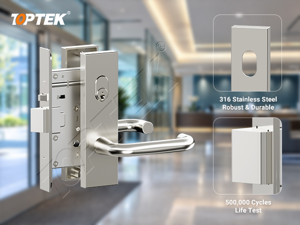
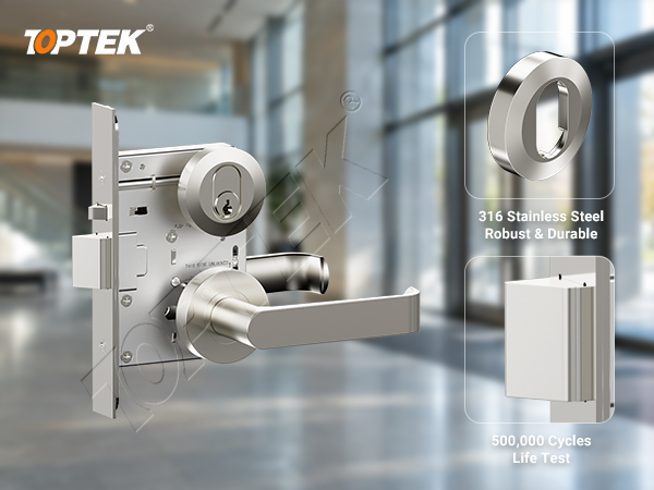
The TKAU6400EC product reference helps identify the presentation being discussed. The purchase description should add the function, version and drawing revision. This prevents a trim photograph from becoming an incomplete substitute for a configured lock order.
Check direction before fixing the trim
Label the controlled outside and the required inside on the door drawing. Confirm the applicable lever-control setting using the instructions for the selected lockcase. Verify both sides before and after fitting the trim. A reversible or configurable mechanism still needs an unambiguous final setting recorded for the installer.
Make oval-cylinder override a defined function
Start with the cylinder format and actuator interface. Confirm its dimensions, retention, projection through the escutcheon or rose, and compatibility with the selected mechanism. “Australian oval” is a format description; it does not establish every actuator, length or keying requirement for a complete lockset.
Describe what the key must do. Does it provide a momentary entry action, change a maintained setting or operate a separate bolt? Record the result after the key is removed and after the door closes again. If a thumbturn or other inside control is included, check its interaction with the lever and selected function.
Demonstrate override in the applicable electrical conditions using the fitted assembly. A key that turns in a loose sample does not prove useful access when the cylinder is installed with the final trim. Binding, excessive projection or the wrong actuator can change the outcome. Include the cylinder and its reference in the approved hardware set.
Key control belongs in the handover package. Identify who holds override keys, who authorizes replacements and how the cylinder references relate to opening numbers. These records make the mechanical access route usable when service staff need it, without relying on memory or a generic label on a key ring.
Define power loss, inside operation and recovery separately
A request for fail-safe or fail-secure operation describes only part of the door function. Write the required outside access condition when the lock loses its supply, then state the inside operation separately. Neither the solenoid label nor an Australian mechanical standard reference decides the building’s access or escape strategy.
Use a scenario table during selection. Include ordinary authorized entry, unauthorized entry, inside operation, mechanical override, loss of lock power and restoration of power. Where an alarm or emergency interface is part of the project, add its approved behaviour and identify the responsible designer. Do not assume it is identical to simply removing power.
Distinguish a controller fault from a supply fault. The controller may stop responding while the lock remains energized. Backup power may preserve operation for part of the system. Define which components are supported and what staff should observe. The result should describe real door movement and access, not just whether an indicator is lit.
Coordinate the controller, cable route and monitoring
Obtain electrical data for the selected powered TKAU configuration. Record supply type and operating range, demand during actuation, any sustained demand, command input and connection details. Do not transfer values from an ANSI or European lock because it uses a similar motor or solenoid description.
The cable route must fit the actual leaf and frame. Check the door power-transfer device, bending and movement allowance, connector access and protection from fixings. Review the supply at the lock during operation. A short bench lead can hide a problem that appears only after the full site cable route is connected.
For monitoring, specify each required condition and ask whether the proposed version supplies it. Door position, lever action and locking-element position are different signals. State which sensor produces each event and how the controller should respond. Do not infer unavailable monitoring from a product-family description.
The electronic mortise lock wiring guide explains route and connector planning. Apply that method using the Australian configuration’s own drawings and ratings. The integrator and lock supplier should agree where their connection responsibilities meet.
Match standards and evidence to the selected assembly
The Standards Australia preview of AS 4145.2-2008 identifies its subject as mechanical locksets for doors and windows in buildings. Use the applicable edition and amendments specified for the project. Do not treat a mechanical lockset reference as certification of an entire electronic access-control installation.
Request model-specific evidence for any mechanical grade or performance claim. Review electrical and system requirements separately. For fire-rated or escape-route openings, obtain the documented hardware and door-assembly compatibility required by the project. A lock’s material description, internal durability test or successful demonstration does not establish that approval.
TOPTEK’s electronic engineering information supports discussion of powered mechanisms and integration. The selected product still needs a controlled drawing and functional specification. Keep capability information, sample results and independent evidence identifiable so buyers can assess each on its proper scope.
Buyer checks, common mistakes and project risks
- Match opening numbers to the exact TKAU version, function, backset, trim and cylinder.
- Verify inside and outside lever behaviour on the fitted assembly.
- Check strike alignment, relatching and the specified override action.
- Compare electrical inputs and supplied outputs with the controller schedule.
- Record relevant fault and recovery results before releasing repeat quantities.
Common mistakes include ordering from a trim picture, copying a competitor’s rating, assuming a solenoid version is always fail-safe, and testing only credential entry. Another avoidable error is machining a replacement door before confirming case depth and cable access. Each can produce rework even when individual components operate correctly.
Use a retained sample and a revision-controlled hardware list to reduce substitution risk. If the cylinder, strike, controller or powered lock version changes, identify which compatibility and function checks must be repeated. An accepted sample should be a reproducible purchasing reference, rather than an unlabelled demonstration unit.
Why TOPTEK and what to send for quotation
TOPTEK’s Australian mortice-lock platform connects escutcheon and round-rose presentation with mechanical, motor and solenoid development options. This supports a joined discussion of commercial door hardware and powered access. It also makes precise configuration essential: the family name should never conceal the function or electrical information needed by the door maker and integrator.
For an initial check, send the opening’s intended inside and outside actions, photographs of the preparation and the proposed control method to the TOPTEK commercial lock and access-control team. Ask for the appropriate model and drawing review before finalizing the door schedule.
Request an Australian project quotation
Include quantities by opening, exact version and function, backset, door thickness, trim, spindle, oval cylinder, strike and finish. Add the controller information, electrical schedule, required monitoring and cable-transfer arrangement. State the evidence requirements, sample purpose, acceptance sequence and delivery stages. Request identification of any option that still requires a choice.
A complete AS 4145 access control mortice lock enquiry connects the physical opening to a repeatable operating sequence. Confirm the mechanical interfaces first, document the powered behaviour, and preserve both through installation and handover. That approach gives procurement, engineering and service teams the same definition of the supplied door hardware.
Frequently asked questions
Does AS 4145 identify the controller connection?
No. Obtain the electrical interface specification for the exact powered lock version and confirm it with the selected controller.
Does the TKAU6400 trim appearance identify the internal version?
No. Specify mechanical, motor or solenoid operation separately, together with the required function and current configuration drawing.
Can any Australian oval cylinder serve as the override?
Do not assume so. Confirm the actuator, dimensions, retention and key action with the selected lockcase and fitted trim.
Are all solenoid versions fail-safe?
No. The actual power-loss behaviour depends on the selected configuration and must be stated independently from inside operation.
What should a replacement project provide first?
Provide photographs and measurements of the door preparation, the required inside and outside functions, cylinder and trim details, and the proposed control method.