
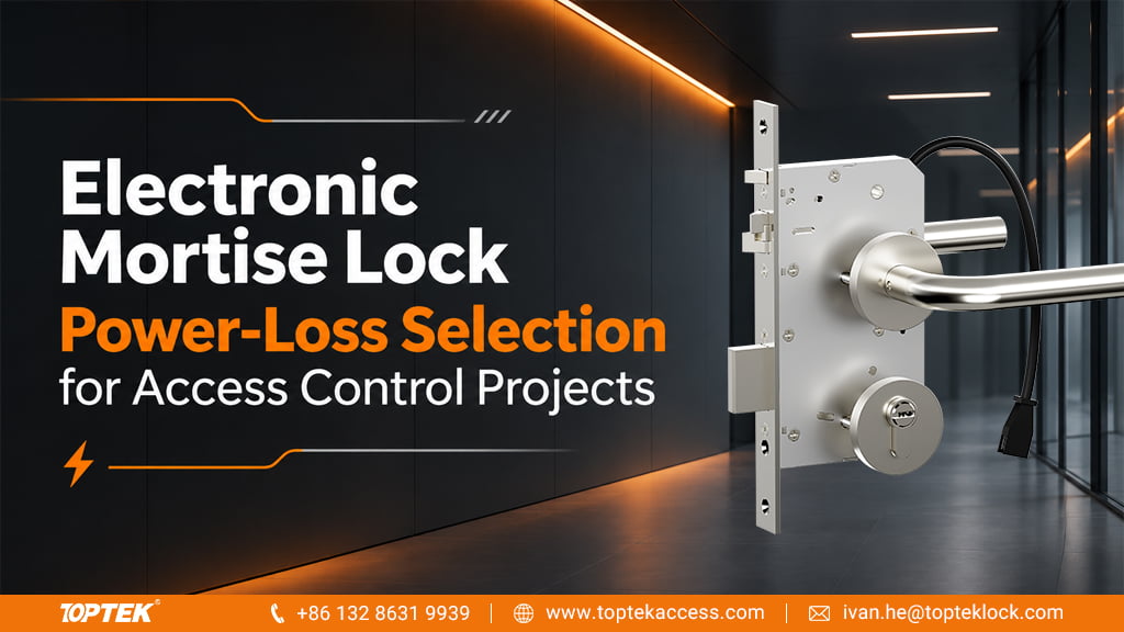

Specify an electronic mortise lock’s power-loss behaviour by describing outside entry and inside exit separately. TOPTEK offers solenoid-controlled lock families and selectable fail-safe or fail-secure configurations. The required function must be attached to the exact model and ordered version, rather than inferred from the words “electronic lock.”
For an access-control integrator or project hardware buyer, the useful decision is what the opening should do when power is no longer reaching the lock. That decision also needs to distinguish a mains outage with backup still operating from complete loss of lock power.
Define the controlled outside function
In a fail-secure configuration, the controlled outside access function remains secured when its power is removed. In a fail-safe configuration, it releases when power is removed. These terms do not, by themselves, describe every bolt, lever or key action in the assembly.
Allegion’s technical explanation of fail-safe and fail-secure functions makes the same separation between secure-side access and egress. Use the definitions to communicate the required behaviour; another manufacturer’s function description is not evidence that a TOPTEK model has the same configuration.
Start with the TOPTEK electronic lock and access control range. Its motorized and solenoid-controlled products provide different mechanisms, so the actuation label alone should not decide the power-off state.
Keep inside exit independent in the specification
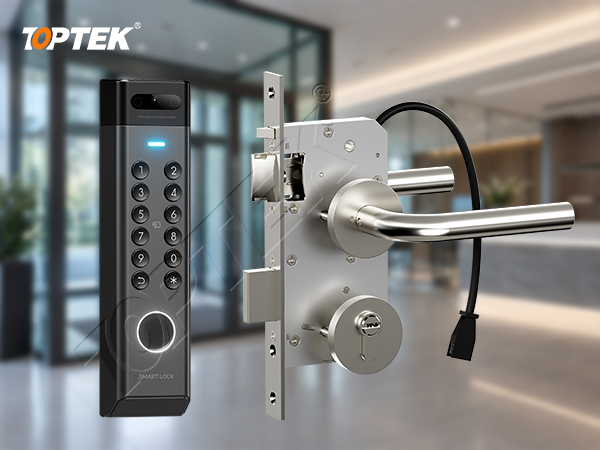
TOPTEK’s self-locking solenoid family includes models such as TKEUS3592. The product concept combines automatic locking on closing, electrically authorized outside entry and mechanical operation from the inside. The order should state the exact version, inside release function and required power-off outside condition together.
This avoids a common ambiguity in purchasing language: “unlock on emergency” might refer to outside re-entry, inside exit, or both. Write which side must operate and what action the person takes. The project designer must resolve the applicable egress, fire and security requirements for the opening; a fail-safe or fail-secure label is not a complete project approval.
Also identify any mechanical key override required from the outside. A keyed cylinder shown in a photograph does not establish which functions it can override. Keep the cylinder and lock function in the same configuration description.
Separate mains failure from loss of lock power
A mains outage does not necessarily remove power at the lock if a battery-backed supply continues to feed it. Conversely, a fault in the final cable or power-transfer path can remove lock power even while the controller remains active. These events can produce different access behaviour and should not be grouped under one unchecked “power failure” box.
| Event | What the project team needs to establish |
|---|---|
| Mains supply lost, backup active | Which components remain supplied and whether authorized entry still operates. |
| No power at the lock | The ordered outside fail state, inside release and any mechanical access route. |
| Reader or network unavailable | The controller’s intended response while the lock may still have power. |
| Emergency input | The approved release sequence and the components that act on that input. |
A network interruption is a useful separate scenario because it can stop credential communication without changing the lock’s supply. Buying a fail-safe lock therefore does not by itself define what happens after a network failure. The controller, power arrangement and commanded function must be specified together.
Match the quotation to the required behaviour
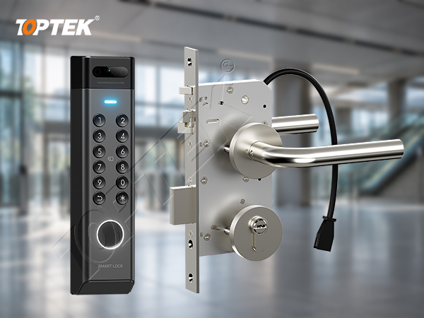
TOPTEK’s engineering and OEM/ODM support starts with requirements and configuration development before sample approval. Use a short opening description to align the proposed lock function, controller interface and power arrangement. Request the model-specific operating and wiring information for that configuration.
Where the project needs status feedback, specify the actual signal and what it means using the electronic lock monitoring guide. A controller’s unlock command is not proof that a latch has retracted or that a door has opened. Verification should follow the approved commissioning procedure for the complete opening, without interrupting a live occupied escape route for an informal test.
Request the appropriate lock configuration
Send the door’s intended use and market, the required outside state with no lock power, and the required inside exit action. Add a candidate model if you have one. Request TOPTEK configuration and operating information for your access-control project. The contact page provides an email route for your opening description and drawings.