
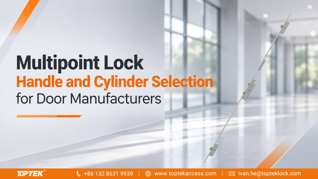

Multipoint lock cylinder and handle compatibility depends on both fit and operation. The handle must drive the correct follower, the cylinder must operate the intended mechanism, and both must fit the finished door. Matching the distance between their centres settles only one of those requirements.
TOPTEK supplies multipoint hardware including PD1000 for patio-door applications and automatic-locking options. For door manufacturers and distributors assembling a hardware set, the practical starting point is the exact lock model and its operating sequence, followed by the handle, spindle and cylinder interfaces.
Use PD1000 to see why centres alone are insufficient
The PD1000 product specifications identify 92 mm handle centres and a 7 mm spindle, together with a 219 mm handle backplate. Those are separate purchase details. A handle advertised only as “92 mm centres” does not establish its spindle section, fixing pattern or suitability for the lock.
For a PD1000-based package, put the 7 mm spindle requirement beside the 92 mm centre dimension in the handle enquiry. Then match the complete furniture drawing, including fixings and usable spindle length, to the door section. The backplate’s overall length does not specify the distance between its fixing holes.
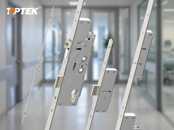
Do not carry a spindle dimension from PD1000 into another multipoint model by assumption. Similarly, a shared centre distance does not make two lock cases, handle sets or cylinder inputs interchangeable. Identify each interface on the drawing for the ordered configuration.
Write what the handle and key must do
TOPTEK’s multipoint development work distinguishes three mechanical operating concepts. An automatic mechanism projects its designated locking points through a closing-trigger action. In a lift-lever mechanism, lifting the handle projects the points and the cylinder can perform a subsequent deadlocking action. In a key-operated mechanism, the cylinder drives the specified locking points.
This distinction changes the handle order. A lever that turns down to release a latch may not provide the upward travel required by a lift-lever mechanism. The cylinder also needs to perform the intended locking and unlocking sequence; its role is not established merely by fitting into the case.
Choose the mechanism through the TOPTEK multipoint range, and record the intended actions from each side of the door. For example, state whether closing alone should engage the locking points or whether the user must lift the handle or turn a key. Assign that sequence to a named configuration before ordering the accompanying furniture.
Measure through the finished door
The finished door thickness includes the hardware build-up at each face. A spindle must engage the follower correctly while allowing the handle furniture to seat and move freely. Cylinder selection likewise needs the inside and outside dimensions relative to its fixing position, rather than overall length alone.
| Component | Order information | Reason it affects the assembly |
|---|---|---|
| Handle and backplate | Centres, fixing pattern and required operating movement. | Aligned visible holes do not establish the movement needed by the lock. |
| Spindle | Cross-section, usable length and engagement for the selected furniture. | It must transmit movement without preventing the furniture from seating. |
| Cylinder | Profile, inside/outside dimensions, fixing position and specified cam interface. | The cylinder must fit the door and operate the correct lock mechanism. |
Use the selected lock’s instructions to establish its cam and rotation requirements. Avoid substituting a cylinder solely because its profile looks familiar. Include any thumbturn, key-control or master-key requirement in the enquiry so that it is considered together with mechanical fit.
Keep the approved combination identifiable
TOPTEK’s door hardware manufacturing process connects component selection with drawings and assembly. For a coordinated order, record the lock model, handle reference, spindle and cylinder configuration together. A later change to the furniture or door thickness should trigger a check of the affected interfaces, even when the lock model stays the same.
TOPTEK’s testing and laboratory capability supports product development, but a generic laboratory description does not establish compatibility of an arbitrary bought-in handle and cylinder. Approve the actual combination against its configuration documents, with the intended operation demonstrated on the representative door.
Request a coordinated hardware selection
For a PD1000 enquiry, start with the model name, finished door thickness and proposed handle drawing or reference. Add the required key or thumbturn operation. Ask TOPTEK for the matching lock, handle and cylinder information. These inputs let the discussion start with the interfaces that matter, without requiring a complete project schedule at the first contact.