
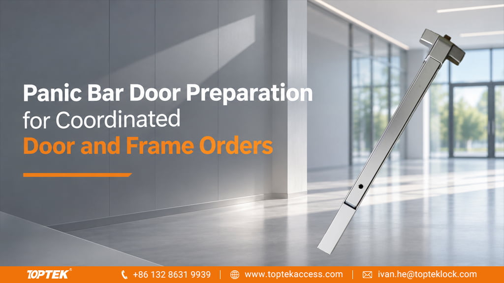

For a door manufacturer, panic bar door preparation should be released as one coordinated door-and-frame drawing. The drawing needs the ordered device, matching strike or rod interfaces, fixing support and outside trim. TOPTEK supplies rim and vertical-rod configurations; selecting the architecture first lets the factory prepare the right interfaces before drilling begins.
A bar can sit correctly on the inside face while the outside cylinder, reinforcement or frame strike still conflicts with it. Treat those components as one opening package. This is particularly useful when the door, frame and hardware arrive from separate suppliers.
Choose the device before releasing the door drawing
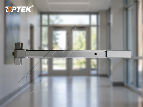
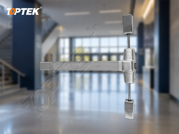
TOPTEK’s F5000 range uses a rim arrangement for single-leaf doors. Its product details include through-bolt fixing and outside access fittings such as a cylinder, trim and lever. The F5600 arrangement adds visible vertical rods and upper and lower latching interfaces. Those differences change which parts of the door and frame must be prepared.
The TOPTEK panic exit device range gives the starting product options. In a rim layout, the latch and strike must meet at the intended frame or mating surface. With vertical rods, the bar position also needs to coordinate with the rod guides and upper and lower interfaces. An approved drawing for one architecture cannot serve as a drilling template for the other.
Bring the two door faces onto the same drawing
The most useful preparation check is a section through the assembled door. It shows whether the inside device fixings, outside trim fixings, cylinder and door reinforcement occupy compatible positions. A front elevation alone can conceal a collision inside a narrow section or leave a fixing supported only by the door skin.
For example, the F5000 details identify through-bolts among the supplied fixing arrangements. That creates a coordination task across the door thickness: the drilling pattern, usable fastener length, outside furniture and reinforcement must agree. A screw pack supplied with a device does not decide how a particular hollow door should be reinforced.
| Drawing item | What to settle before machining |
|---|---|
| Inside device | Exact model and variant, mounting references, end support and clearance to nearby hardware. |
| Door construction | Thickness, core or section, reinforcement locations and the specified fastening method. |
| Outside trim | Entry function, cylinder or spindle interface, fixing positions and clearance through the door. |
| Frame and mating surfaces | Strike location and fixing support; upper and lower interfaces where rods are used. |
Set the operating height from the project-approved opening design and the applicable installation instructions. The height of the device case, the touchpad length and a suggested mounting position describe different things; none should be substituted for the required operating-height dimension.
Check the opening in its assembled condition
A workshop review should include the leaf, frame, selected strike, outside trim, closer and seals that affect closing. The PEDAM002 product page and PEDAM001 vertical-rod page help identify the relevant product arrangement; the model-specific installation information controls the preparation.
On the representative opening, confirm that the device mounts without distortion, the outside fitting operates its intended function, and the latch or rods align during closing. If the sample requires a changed hole position, shim or strike location, put that change into the drawing before the batch is released. Otherwise the working sample and the production instruction describe different assemblies.
This is where preparation coordination helps purchasing: the order specifies an identifiable configuration that the door factory can reproduce. It also gives the hardware supplier a defined starting point when a later order uses a different door thickness or trim.
Use TOPTEK’s engineering process to align the order
TOPTEK’s OEM/ODM engineering support includes configuration and drawing development, sample approval and production change management. For an exit-device package, use that process to agree the device and interfaces before committing the door preparation. Retain the approved drawing revision with the purchase order and sample reference.
For fire-rated or escape-route openings, the specified assembly and preparation must remain within the applicable product and doorset documentation. A general product photograph or a different hardware model’s approval cannot establish that scope.
Request the preparation information for your opening
Send TOPTEK the door-and-frame section, door thickness and required outside entry function. Include the device model if already selected. Request the matching product and preparation information so your team can coordinate the hardware package before releasing machining. The contact page also provides a direct email route for drawings.