
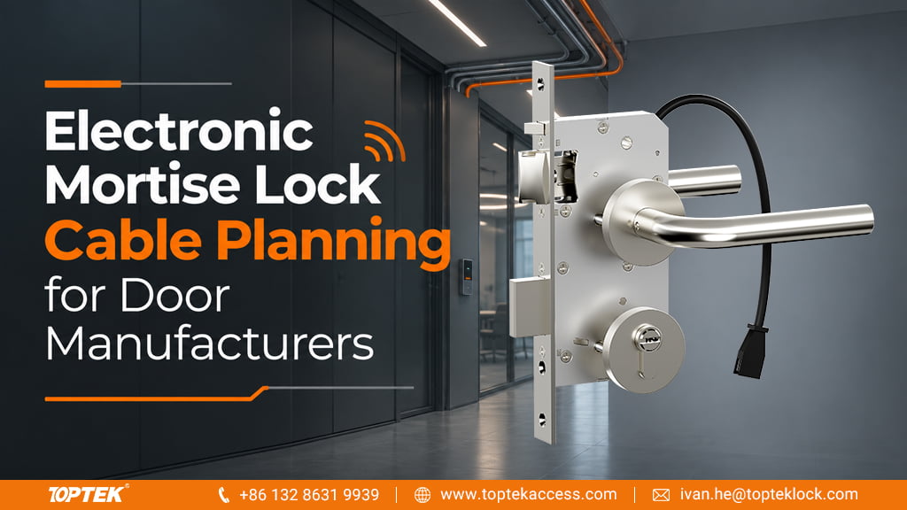

Plan electronic mortise lock wiring from the selected lock’s connection drawing and the required door functions before making the harness. Identify the power circuit, control connections and any monitoring circuits separately. Then confirm the connector, cable route and door movement together. The appearance of a plug or the number of visible wires does not define the electrical interface.
For door manufacturers, this is a coordination task between the lock supplier and access-control integrator. A clear cable schedule allows the door preparation and harness to follow the agreed lock configuration, reducing avoidable changes after the leaf has been manufactured.
Start with the lock function and exact variant
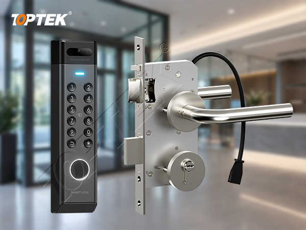
TOPTEK’s electronic lock and access-control range includes motorized and solenoid-controlled mortise-lock families. The TKEUS3592 solenoid-controlled self-locking model is one example of a defined product reference. Select the variant and intended operation first, then obtain its applicable electrical connection drawing.
State what the access-control command should do and which conditions the system needs to monitor. A powered unlocking function and a status output have different roles. A monitoring contact must not be treated as a power input, and an available status option should not be assumed to be included in every supplied variant.
Create a connection schedule before the harness drawing
| Circuit or interface | Confirm for the selected supply |
|---|---|
| Lock power | Rated supply, polarity where applicable, operating and peak-current requirements, and permitted voltage at the lock. |
| Control connection | Required input type and the interface supplied by the controller or relay. |
| Monitoring connections | Available functions, contact or output type, contact ratings where applicable, and terminal assignment. |
| Connector and harness | Mating connector, pin assignment, cable specification and the drawing revision used by both suppliers. |
| Frame-to-leaf route | Transfer arrangement, mounting position, usable cable space and movement of the actual door. |
The schedule should name both ends of each circuit. A note reading “six-core cable to lock” leaves the installer to determine what those cores do. A function-by-function record makes the required interfaces explicit and gives the harness supplier a controlled reference.
Do not choose conductor size from a typical lock example. The integrator should calculate the supply arrangement using the selected lock’s electrical requirements, cable run and allowed voltage loss. Confirm the requirement during actuation as well as steady operation where the device has different current demands.
Plan the moving cable route as part of the door
TOPTEK supplies an electric door-loop solution for routing protected wiring between the frame and leaf. Its role is to provide a protected path for the cables crossing the moving interface. Confirm whether the order includes conductors and connectors or only the protective transfer assembly.
The transfer product must accommodate the agreed cable and door geometry. Check the cable path from closed position through the intended opening range, including entry points, termination space and strain relief. A cable that reaches the terminal with the door closed can still be pulled or pinched when the door opens.
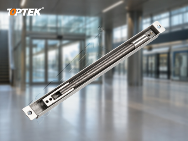
The door-loop and power-transfer-hinge selection guide covers transfer-device choices. For a useful industry reference, SDC’s power-transfer-loop documentation also distinguishes surface and concealed arrangements. The final selection still depends on the product dimensions and cable requirements of the particular opening.
Check the installed combination before repeating the harness
Use a representative door and the specified lock, controller interface, supply and harness. Compare the connections with the agreed drawing, confirm the intended operation, and exercise the full door movement while checking the cable route. Where monitoring is specified, verify each required output against the actual condition it represents.
Retain the accepted connector and cable revision with the lock order. A later change to a connector, monitored function or power requirement should trigger a review of the corresponding harness interface before the same cable assembly is ordered again.
TOPTEK’s commercial door hardware manufacturing support connects product configuration with OEM/ODM supply. Providing the lock reference and connection schedule together gives the discussion a concrete starting point, especially when the door brand and access-control integrator are separate businesses.
Request a lock and harness interface review
Send TOPTEK the selected lock reference, door section and required control and monitoring functions. Include the controller interface, proposed cable run, transfer arrangement and order quantity. Request the applicable connection drawing and a confirmed supply scope before releasing the harness for manufacture.
Frequently Asked Questions
Does a door loop include the lock wiring?
Confirm the supply scope. A protective transfer assembly may be supplied separately from the conductors, mating connectors and completed harness required by the selected lock.
Can a familiar connector be wired from its appearance?
No. Use the connection drawing and pin assignment for the exact lock variant. Match the mating connector and circuit functions before energising the assembly.