

TL;DR
Specify an electric power transfer hinge from the circuit schedule and the physical opening. Count every required conductor, define each circuit and load, confirm voltage-drop limits, connector and splice strategy, hinge position, door swing, reinforcement and cable routing. Then test continuity and operation through the full door movement. Do not infer conductor count, gauge, current capacity or rating from a product image.
Start with the Hinges and Door Power Transfer product hub, then use this narrower guide to define the required function and approval evidence.
Quick Answer
Create one opening wiring table that names each conductor pair or signal, source, destination, voltage or signal type, expected current, monitoring purpose and spare requirement. Match that table to the exact hinge data and door preparation. Bench-test the identified hinge, then commission the complete lock, monitoring and egress sequence on the installed door.
Build the conductor schedule before selecting the hinge
An access-controlled opening can require conductors for lock power, lock control, request-to-exit, door position, latch or bolt monitoring, reader or other project-specific functions. Count circuits rather than guessing from the number of devices. Some signals may share an approved common, while others need isolation or a dedicated pair. The system designer must define that architecture.
For every conductor, record source, destination, function, voltage or signal type, normal and peak current where applicable, polarity, shielding or grounding requirements, permitted splices and spare capacity. The electric hinge supplier can then confirm a matching configuration. Missing fields should stay open; they must not be filled from a similar product photograph.
Check load, voltage drop and connector responsibility
The circuit must deliver the required condition at the lock after cable length, conductor resistance, connectors and moving interfaces are considered. A nominal power-supply voltage alone does not prove that the installed device receives the required voltage under load. The access-control designer or electrical contractor should perform the applicable calculation for the complete run.
Define who supplies the frame-side cable, door-side cable, connectors and transition to the lock. Mark accessible service points and avoid concealed site splices that cannot be inspected. If a shield or protective earth is required by the system design, show how continuity is maintained without making an unsupported assumption about the hinge construction.
Coordinate hinge position, handing and door movement
A power-transfer hinge carries the door mechanically while routing conductors across the moving interface. The exact hinge position must agree with the door and frame preparation, reinforcement, swing and cable entry locations. The lead arrangement must allow installation without twisting, pinching or pulling the conductors as the door opens.
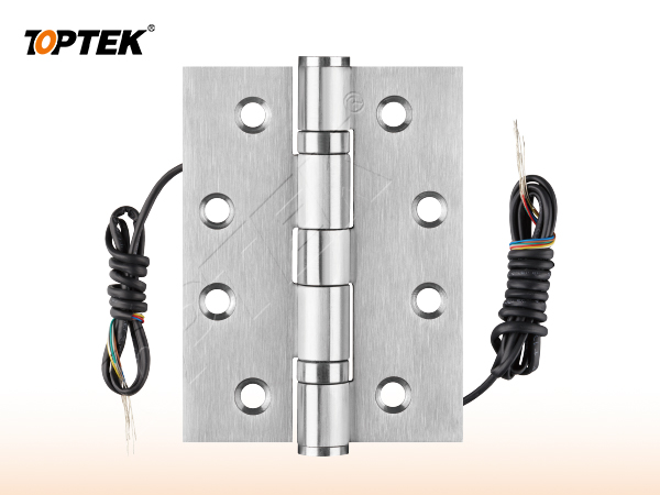
Use the TOPTEK Electric Butt Hinge 2BB page as a current product-family reference. Confirm the exact conductor option, hinge dimensions, hand or orientation, connector arrangement, finish, mechanical selection and evidence on the quotation and drawing.
Test the moving circuit, not only static continuity
A static meter check with the door open in one position does not reproduce service movement. Test continuity and, where appropriate, resistance or voltage at closed, intermediate and fully open positions without exceeding the approved range. Operate the door repeatedly while monitoring the controlled device and return signals for intermittent behaviour.
The commissioning sequence should also prove authorised entry, locked state, inside egress, power-loss behaviour, mechanical override and monitoring states that apply to the opening. The hinge transfers conductors; it does not decide the life-safety or security sequence. Keep the witnessed test linked to the opening number and wiring revision.
| Wiring field | Project input | Verification |
|---|---|---|
| Circuit map | Each power, control and monitoring path | Approved point-to-point diagram |
| Electrical load | Voltage, current, duty and voltage drop | Loaded measurement at the door |
| Conductors | Count, size, polarity, shield and spares | Exact hinge configuration |
| Movement | Swing, hinge position and cable path | Continuity through full travel |
| Connections | Frame side, door side and service points | Accessible labelled inspection |
| System states | Entry, egress, power loss and monitoring | Witnessed opening test |
Connect wiring guidance to commercial access-control pages
This article serves the technical wiring question. Broader searches for commercial locks and access control manufacturing belong to the integrated commercial page. Searches for a commercial door hardware manufacturer belong to the hardware capability page. Those pages should link to this guide when buyers need the detailed interface method.
The separation protects Canonical ownership: the commercial pages prove supplier scope, while this guide explains conductor planning, door movement and approval tests. Product and resource links provide the evidence path. Repeating one generic manufacturer paragraph on every technical page would weaken that structure.
Approve the opening as a system
Hinges and Door Power Transfer is only one part of the opening. The door leaf, frame, strike or rod interfaces, trim, cylinder, closer, power components where applicable, and the installation conditions all influence the result. TOPTEK publishes electric butt hinge references within its precision hinges and door power-transfer family. Confirm conductor count and size, circuit limits, hinge dimensions, bearing arrangement, finish, preparation, connectors and model-specific evidence for the exact quotation. A catalogue family name cannot replace a coordinated opening schedule.
Give every opening a unique number. Attach the current elevation, door and frame construction, thickness, swing, handing, hardware interfaces, finish, evidence requirements and sample reference. When one field changes, reopen the affected checks instead of assuming that the earlier approval remains equivalent.
Use a state-based approval test
Write the normal, locked, authorised-entry, emergency-egress, override and abnormal states that apply. For each state, record what the user does and what each latch, bolt, rod, lever, key or electrical input must do. Mark a state N/A when it truly does not apply; a blank field hides a decision.
Operate the labelled sample in the same sequence. Review from both sides of the door, then repeat the critical checks in representative preparation. Photograph labels and interfaces, but preserve the signed state table as the controlling approval record. Appearance alone cannot prove function.
Separate product evidence from project approval
A certificate, test report or declaration applies only to the product, construction, standard and configuration named in its scope. A project still needs to determine whether that evidence is the document it requires. Request current original records and compare model identifiers with the quotation, drawing and sample.
Do not turn an internal development test, a website badge, a similar model or a customer statement into third-party certification. If evidence remains open, record the missing document, responsible reviewer and due date. This guide intentionally avoids unsupported cycle, load, corrosion, fire or material claims.
Buyer approval checklist
- Opening number, door type, frame and swing
- Plain-language operating sequence from both sides
- Exact product, trim and interface references
- Door preparation and installation tolerances
- Required model-specific evidence and revision
- Labelled sample and acceptance owner
- Packaging, site inspection and handover controls
- Repeat-order change-control reference
Common mistakes and project risks
Common mistakes include selecting by hinge appearance, counting devices instead of circuits, omitting current and voltage-drop checks, treating signal and power conductors as interchangeable, twisting leads during installation, locating connectors where they cannot be serviced, failing to coordinate reinforcement, and testing continuity at only one door position.
The practical consequences can include re-machining, replacement hardware, revised wiring or keying, delayed inspection and uncontrolled site modification. Stop approval when the operating sequence, physical interface or evidence scope is unclear. A question recorded before production costs less than an assumption discovered across installed doors.
TOPTEK evidence and product scope
TOPTEK uses product-family material, model images and internal engineering observations to frame the buyer questions in this guide. These sources support a configuration discussion; they do not make every option, dimension or approval universal. The supplied configuration still has to be identified on a current drawing.
Use the TOPTEK resources centre for product documents and the applicable evidence request. Where a source describes internal testing, treat it as internal verification unless an original third-party document for the quoted configuration is separately reviewed.
RFQ checklist
- Opening number, door/frame construction, swing and hinge schedule
- Circuit list with source, destination and function
- Voltage, signal type, current, polarity and voltage-drop basis
- Required conductor count, size, shield/ground and spare policy
- Hinge position, cable entries, connectors and service access
- Mechanical hinge selection, finish, evidence and commissioning test
- Required evidence list and market/project basis
- Sample quantity, acceptance tests and owner
- Drawing, quotation and order revision control
- Production labels and packaging requirement
Why TOPTEK: turn selection into a controlled record
TOPTEK can review a marked-up schedule, translate shorthand into operating and interface questions, and identify missing information before quotation. The objective is not to guess the designer’s decision; it is to give the responsible parties a clear configuration to approve.
Quotation, drawing, sample label and order acknowledgement should carry the same reference. This lets door manufacturers, distributors, integrators and project teams detect substitutions or later changes. It also creates a practical basis for repeat-order inspection.
Two-level CTA
For an initial review, send the opening list, door images or elevations and the required user sequence. Highlight unknowns. TOPTEK can return a focused question list without presenting assumptions as confirmed facts.
For a formal RFQ, submit the approved schedule, drawings, interfaces, evidence requirements and sample protocol through the TOPTEK contact page. Request a configuration-specific response and identify the person authorised to approve deviations.
Conclusion
Good hardware selection is a controlled translation from user behaviour to product configuration. Define the function, verify the physical interfaces, check the applicable evidence and demonstrate the identified sample. Do not let a general product name carry decisions it cannot contain.
Preserve the result through procurement, production, installation and handover. That discipline reduces avoidable replacement risk while keeping every TOPTEK statement inside the evidence and configuration actually reviewed.
Frequently asked questions
How many conductors does an electric power transfer hinge need?
It needs enough approved conductors for every defined power, control and monitoring circuit, plus any specified spare capacity. Count from the point-to-point wiring schedule, not the device count alone.
Can conductor gauge be chosen from the hinge image?
No. Confirm the exact hinge data, circuit current, cable length, voltage-drop limit, connector arrangement and applicable system requirements.
Why must continuity be tested while the door moves?
Door movement can expose intermittent faults caused by routing, twisting, pinching, lead tension or connection problems that a static test may miss.
Does an electric hinge determine fail-safe or fail-secure operation?
No. The hinge transfers conductors. The selected lock, control logic, power system and approved opening design determine the required operating states.
What should an electric hinge RFQ include?
Include the opening and hinge schedule, circuit map, electrical values, conductor requirements, cable entries, connectors, reinforcement, finish, evidence and commissioning sequence.