

TL;DR
- Record whether the fault follows door movement, load activation or both.
- Have a qualified technician isolate power before continuity or resistance checks.
- Test identified conductor paths and accessible connections separately.
- Use product-specific limits for loaded measurements; a continuity beep is not a current-capacity approval.
- Preserve the failed part and the test record before ordering a replacement.
Quick Answer
How should electric hinge intermittent power be checked? Start with a labelled circuit drawing and a repeatable symptom record. A qualified technician should inspect accessible terminations and cable routing, isolate the relevant circuit, and check each designated conductor through the permitted door movement. Compare results with the hinge and connected equipment instructions. If continuity remains stable, further diagnosis may need to examine voltage under load, controller behaviour or the lock itself. Replace the component supported by the evidence, then repeat the functional checks with the final wiring secured.
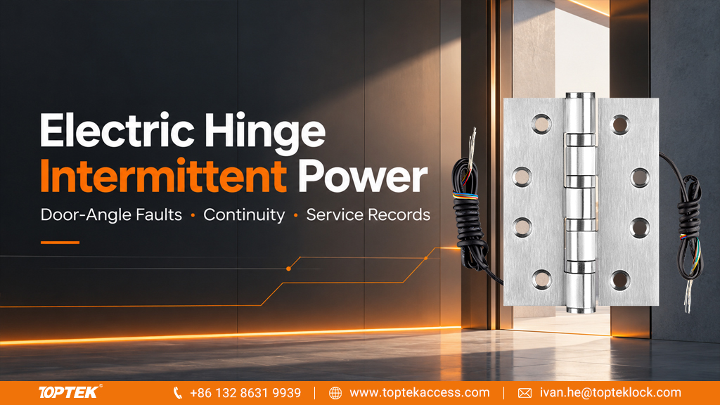
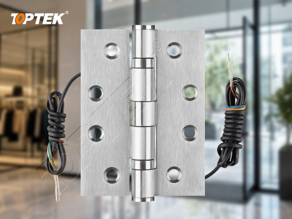
The TOPTEK hinge and door power transfer range includes different mechanical and electrical arrangements. Identify the installed version before requesting service parts or assuming that a similar-looking hinge has the same wiring.
Make the intermittent symptom repeatable
“Works sometimes” is difficult to diagnose. Record whether the fault appears while opening, closing or holding the door still. Note the approximate leaf position and whether the problem repeats at the same point. A short video showing the movement and the affected indicator can be useful when paired with the door number and a description of the test conditions.
Separate loss of lock power from a change in a monitoring signal. A door-position contact may change state intentionally as the door opens. A controller event may therefore be normal even though it occurs at a repeatable angle. Identify which device produces the signal and what the system expects before treating the event as broken wiring.
Also note whether other openings share the symptom. Several doors failing when a common supply is loaded suggest a different investigation from one opening that fails only during movement. These are directions for testing, not conclusions. Keep the observed facts distinct from the technician’s working explanation.
| Pattern | Record | Area to investigate |
|---|---|---|
| Fault at a repeatable angle | Opening direction and position | Moving conductor path, lead routing and nearby terminations |
| Fault only when the load activates | Command, load and measured supply condition | Supply, voltage drop, connections and load requirements |
| Monitoring changes but lock power remains | Signal name and expected state | Sensor function, signal wiring and controller interpretation |
| Several doors fail together | Shared circuits and event timing | Common supply or control equipment |
Define the circuit and a controlled test window
Prepare a diagram from the power source to the door-mounted device, including intermediate connectors, the hinge and the return conductor. Mark monitoring circuits separately. Wire colour alone is not a complete circuit identity, particularly where multiple installers have joined different harnesses. Assign terminal or connector references at both ends.
Arrange testing with the person responsible for building access and door operation. Follow the site’s maintenance controls and the connected equipment instructions. Do not leave an opening with required security or escape functions disabled. Electrical measurements and disconnection should be performed by a qualified person using suitable equipment.
Fluke’s continuity-testing guidance explains that power must be removed for continuity checks and that meter indications depend on the instrument. Treat continuity as a check of a conductive path, not as proof that the circuit will deliver the required current. Use the meter’s instructions and the relevant equipment procedures.
Inspect leads and terminations before condemning the hinge
Look for visible pinching, insulation damage, loose connector retention and cable pulled tight near the hinge recess. The inspection should cover both frame and door sides. A hinge can be electrically intact while a nearby connection opens as the door moves. Conversely, a tidy visible installation cannot rule out a fault inside the moving path.
Compare the installed routing with the approved preparation drawing. Confirm that the lead path has the specified protection at metal edges and sufficient space for the approved installation. Do not enlarge preparation or change a fire-door detail merely to create more cable room. Refer any preparation conflict to the door and hardware supplier.
Photograph the arrangement before disturbing it. Re-seating a connector may temporarily remove the symptom, making the original cause harder to identify. Record what was changed and whether the same movement test was repeated afterwards. A repair history that says only “connection checked” is less useful than one that identifies the connector and the observed defect.
Separate continuity checks from loaded performance
With the relevant circuit safely isolated and disconnected as required by the equipment instructions, the technician can check the designated conductor paths. Define the boundaries of each measurement: hinge alone, hinge plus its connectors, or the complete run. Without those boundaries, an open-circuit result cannot identify which part requires replacement.
Keep the test connections secure while the door moves through its permitted range. Record the result for each conductor and the positions associated with a change. Avoid pulling on the hinge leads as a way to reproduce the fault. If the test equipment loses contact during movement, repeat the setup before attributing the reading to the product.
A low-current continuity check may miss a connection that becomes troublesome under the real load. Once the circuit has been correctly restored, a qualified technician may need a separate loaded-voltage investigation using the approved procedure. Compare supply and load conditions with the lock and power-source requirements. Never switch a meter into resistance mode on an energised circuit.
Do not invent a universal resistance threshold or minimum voltage for every electric hinge. Conductor length, connections, load behaviour and the selected products matter. The power transfer hinge wiring guide provides the broader configuration context; troubleshooting should use the actual circuit and its documented limits.
Match the replacement to the full configuration
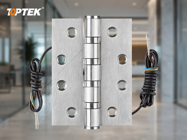
TOPTEK’s 2026 catalogue presents electric 2BB and 4BB hinge families with different mechanical dimensions and conductor configurations. The same basic model designation can appear in more than one configuration. For a service order, state that the hinge is electrical and provide its dimensions, leaf thickness, conductor arrangement and drawing revision.
The Electric Butt Hinges 2BB product page is a useful family reference, but a replacement should match the approved assembly record. A change from one bearing arrangement to another is not an electrical repair specification. Hole positions, leaf thickness, door preparation and the circuit requirements all still need review.
Ask for the applicable electrical ratings and installation instructions for the supplied version. A wire count does not tell you its permissible current, and the presence of conductors does not establish a built-in monitoring switch. Do not transfer another manufacturer’s ratings or a conventional hinge’s evidence to the selected electric hinge.
Retest the final installation and retain the evidence
Repeat the relevant checks after the final connections are secured and covers or access points are restored. A successful bench test does not show how the leads behave inside the completed door preparation. Operate the door through the approved movement and verify the intended electrical functions under the agreed acceptance procedure.
Record the replaced component, wiring references, measurement conditions and observed outcome. Keep the removed part labelled with its door number and fault description. For recurring failures, compare records across openings for common preparation, installer practices or component batches. Repeated replacement without a usable record can hide an installation problem.
Common mistakes include declaring the hinge defective from one controller message, measuring continuity while other circuit paths remain connected, ordering by appearance, and closing the job before retesting with the wiring secured. Each can produce an apparently successful repair that fails again when the door returns to normal service.
TOPTEK service evidence and RFQ checklist
Why TOPTEK for the review? The product range includes conventional hinges, electrical butt hinges and door-transfer products, allowing the enquiry to distinguish the mechanical support from the required electrical path. Use the catalogue and product drawings to define the assembly, then request evidence that applies to that version and application.
Ask how the supplied configuration will be identified within the TOPTEK quality-management process. For a wider commercial door hardware programme, connect the service record to the purchase reference and spare-parts schedule so that replacement orders remain consistent.
- Door number, hinge reference, dimensions, leaf thickness and installation drawing.
- Conductor count, circuit assignments, connector references and required electrical ratings.
- Connected lock or device, power source and control arrangement.
- Fault pattern, movement direction, approximate angle and whether the load was active.
- Inspection photographs and technician measurements with clear test boundaries.
- Quantity, service deadline, required evidence and the final acceptance procedure.
Frequently asked questions
Does a fault at one door angle prove the electric hinge is damaged?
No. It suggests a movement-related issue, but nearby leads, terminations or an intentional monitoring change must also be considered.
Can continuity be tested with the circuit powered?
No. A qualified technician should isolate the relevant circuit and follow the meter and connected equipment instructions before continuity or resistance testing.
Does a continuity beep prove the hinge can supply the lock?
No. It indicates a conductive path under the meter’s test conditions. Loaded performance and electrical ratings require separate checks.
Can an electric 4BB hinge replace any electric 2BB hinge?
No. Confirm mechanical fit, door preparation, conductor configuration, electrical limits and application evidence for the proposed replacement.
What is the most useful information in a service enquiry?
Provide the exact component references, circuit diagram, repeatable fault pattern, installation photographs and technician measurements with defined test boundaries.
Conclusion and request a configuration review
Electric hinge intermittent power needs a repeatable observation and a clearly defined test path. Check the surrounding connections, separate continuity from loaded operation, and identify the full mechanical and electrical configuration before ordering. Retesting the completed installation is what turns a replacement into a documented service result.
For an initial review, send TOPTEK the hinge reference and a short description of the movement-related symptom. For a formal quotation, add the drawings, circuit requirements, quantities and acceptance criteria. TOPTEK is your Commercial Door Hardware Reliability Solution.