

CE Mortice Lock Sizes Guide: Backset, Centres, Case Depth and Door Preparation
Focus: mortice lock sizes
CE Mortice Lock Buyer Guide | 28 August 2026
Author: Ivan He, TOPTEK | Technical review status: final engineering sign-off required before publication.
TL;DR
- “Mortice lock size” is not one number. It is a coordinated set of reference dimensions.
- Backset, centre distance and case depth describe different parts of the lock and must not be interchanged.
- Forend and strike dimensions connect the lock body to the prepared door edge and frame.
- Follower, spindle and cylinder details belong in the same size record because they control trim compatibility.
- Approve a dimensioned drawing and production-intent sample in the representative door and frame before bulk ordering.
Quick Answer
How do buyers specify mortice lock sizes? Record the lock function, backset, lever-to-cylinder or lever-to-keyhole centres, total case depth and height, forend dimensions, follower square, cylinder interface, strike geometry, door thickness and actual door/frame preparation. Mark every datum on a drawing. A single number such as “72 mm” cannot identify the complete lock.
1. Why “Mortice Lock Size” Is a Measurement System
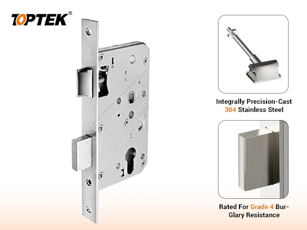
Buyers often ask for a 72 mm, 85 mm or 60 mm mortice lock. That description can be useful, but it does not define a purchase-ready product. Different numbers may refer to centre distance, backset, case depth, forend width or another feature. Two lock bodies can share one headline dimension while differing in function, case envelope, spindle interface, forend or strike.
The safe method is to treat the lock as a coordinate system. Establish the finished door edge as a datum, then identify the axes of the lever follower, cylinder or keyhole, latchbolt and deadbolt. Add the outer case envelope, forend and strike. This lets the factory, door manufacturer, installer and hardware consultant discuss the same geometry.
This guide owns the broad mortice lock sizes search intent. More detailed questions remain on TOPTEK’s case-depth, replacement, forend/strike and cylinder/spindle guides so one page does not compete for every measurement query.
2. Mortice Lock Size Map
| Dimension | What it describes | Buyer risk if omitted |
|---|---|---|
| Backset | Door-edge/forend reference to operating axis | Lever or cylinder sits in the wrong position |
| Centres/PZ | Follower axis to cylinder/keyhole axis | Trim apertures do not align |
| Case depth | Overall lock-body depth | Conflict with stile, glass or reinforcement |
| Case height | Overall lock-body vertical envelope | Pocket or internal hardware conflict |
| Forend | Door-edge plate length, width, thickness and shape | Recess and screw holes do not match |
| Follower | Square interface receiving the spindle | Lever play, binding or no operation |
| Strike | Frame plate and keep geometry | Latch/deadbolt will not engage correctly |
3. Measure Backset from a Defined Datum
Backset positions the operating axis behind the door edge. On a European sash lock drawing, it commonly relates the forend or door-edge reference to the lever follower axis, while the cylinder axis often shares that horizontal position. Do not assume every drawing uses the same start surface; confirm whether the dimension begins at the visible forend face, the door edge behind it, or another manufacturer datum.
Backset affects handle clearance, door stile strength, escutcheon position and the relationship to glazing or reinforcement. TOPTEK’s verified EN72SL product page lists backset options from 40 to 100 mm. This is a range of selectable configurations, not a promise that every function, forend or project condition uses every option.
Backset measurement check
- Mark the finished door-edge datum.
- Measure perpendicular to the exact follower or cylinder centreline.
- State whether the forend thickness is included.
- Compare the measurement with the product drawing.
- Check lever/knob clearance from the frame and stop.
4. Understand Centres or PZ
Centre distance is the vertical spacing between two operating axes. For many Euro-profile sash locks, the familiar 72 mm or 85 mm value is measured from the lever follower centre to the cylinder centre. Bathroom or keyhole functions can use a different lower interface and therefore require a clearly labelled drawing.
A 72 mm centre distance does not mean a 72 mm backset, a 72 mm case depth or a particular spindle square. It simply coordinates the lock apertures with the handle plate, rose/escutcheon and cylinder trim. If a plate handle is used, its drilling and profile cut-out must match the selected centres exactly.
TOPTEK’s verified EN 12209 mortice lock category includes several functions. Buyers should not transfer the centres or interface of one function to another merely because the outer case looks similar.
5. Case Depth Must Fit the Door Profile
Case depth is the full horizontal envelope of the lock body. It must fit inside the door stile with enough surrounding material or reinforcement for the door design. The usable cavity is not always equal to the visible stile width. Glass lines, internal channels, edge reinforcements, seals, wiring and fixing zones can reduce the available space.
Compare the complete case drawing with a section through the exact door. The review should include the body, projecting latch or bolt in relevant states, fixing screws and cylinder fixing screw. For narrow metal or aluminium profiles, a few millimetres can decide whether the installation is viable.
Do not infer case depth by subtracting backset from a catalogue headline number. Use the manufacturer’s dimensioned drawing and check tolerances. The dedicated case-depth guide can remain the detailed canonical reference while this page explains how that value belongs in the whole size system.
6. Forend Dimensions Control the Door-Edge Preparation
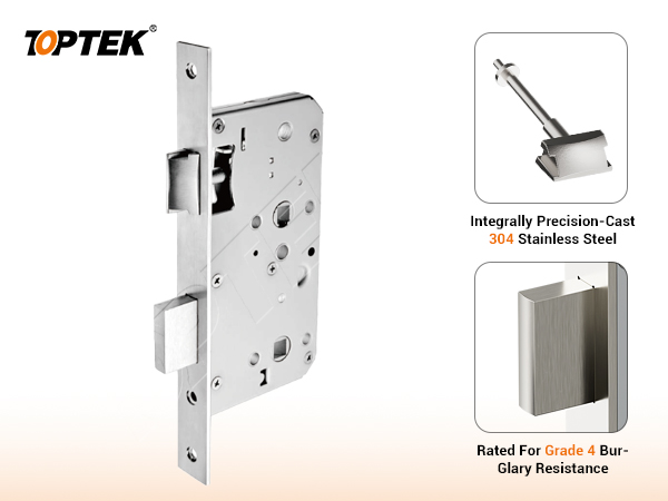
The forend is the plate visible on the door edge. Record its total length, width, thickness, square or rounded corners, screw positions, latch and deadbolt openings and finish. A lock body can fit inside the pocket while its forend still fails to sit flush in the existing recess.
For replacement work, measure the prepared recess and the removed forend separately. Previous site modifications can make the opening larger than the original component. Do not design the new lock around an irregular recess without confirming how the door edge will be restored.
The strike must be reviewed with the forend because both establish the latch and deadbolt relationship across the door gap. Use TOPTEK’s detailed forend-and-strike guide as the canonical source for alignment and preparation controls.
7. Follower, Spindle and Cylinder Are Size Interfaces
The follower square defines the spindle interface. TOPTEK EN72SL information lists 8 × 8 mm and 9 × 9 mm follower options. That choice is independent of the 72 mm centres. The handle schedule must state spindle square, effective length, solid or split architecture where relevant, lever springing and finished door/trim thickness.
A Euro-profile cylinder also needs oriented A/B lengths measured from the fixing-screw centre to the finished trim faces. Confirm cam geometry, function, keying and projection. A correct body opening does not prove that the cam or length will operate safely.
For a complete set, relate these values to the verified EN 1906 lever handle range and EPCVK6P cylinder reference, then approve the exact models together.
8. Strike, Frame and Door Gap
Strike dimensions include plate length, width and thickness, lip or keep geometry, screw positions and the locations receiving latch and deadbolt. Frame material matters: timber, hollow metal and aluminium profiles can require different preparation and fixing strategies.
Measure the actual closed-door gap and account for seals, tolerances, hinge adjustment and expected movement. Confirm that the latch enters the keep without dragging and that the deadbolt reaches full projection. Enlarging the strike opening after installation may conceal an alignment error but does not create a controlled approval.
9. Buyer Measurement Checklist
- Door number, function and handing
- Finished door thickness and edge construction
- Frame section, stop, seals and closed-door gap
- Backset with stated datum
- Follower-to-cylinder/keyhole centres
- Total case depth and height
- Forend length, width, thickness and corner shape
- Follower and spindle square
- Cylinder profile, cam and oriented A/B length
- Latch and deadbolt projection
- Strike plate and keep geometry
- Screw positions and fixing substrate
- Existing preparation photos with a scale
- Dimensioned drawing revision and sample owner
10. Common Measurement Mistakes
- Using “72 mm lock” as a complete specification.
- Confusing backset with case depth.
- Measuring to the edge of a hole instead of its centreline.
- Ignoring whether the forend thickness is included in the datum.
- Selecting from the faceplate only.
- Assuming door thickness determines the lock-body size.
- Copying a cylinder length without the finished trim.
- Approving a loose lock rather than the fitted opening.
11. Project Risks and Controls
| Risk | Likely outcome | Control |
|---|---|---|
| Ambiguous datum | Repeated dimensional mismatch | Mark axes and references on drawing |
| Case/stile conflict | Door cannot be prepared safely | Overlay case drawing on door section |
| Wrong centres | Handle plate and cylinder do not align | Approve trim and lock drawing together |
| Strike misalignment | Binding or incomplete engagement | Fitted door/frame sample |
| Evidence overreach | Unsupported compliance claim | Verify exact scope through TOPTEK Resources |
12. TOPTEK Evidence and Product Range
This guide uses TOPTEK’s current EN 12209 product materials, CE certificate file, verified product images, brand context and live product pages. The internal source identifies 72, 78 and 85 series functions; the exact combination of function and dimensions remains an order-level decision.
TOPTEK internal laboratory verification must remain labelled as internal and is not substituted for third-party certification. Certificate or test claims should be used only when the exact ordered model and scope are confirmed. Buyers can start from the TOPTEK product portfolio and request the latest dimensioned drawing for the selected configuration.
13. Mortice Lock Size RFQ Checklist
- Project, market, quantities and door references
- Required function and access logic
- Door and frame sections
- Backset, centres, case depth and case height
- Forend and strike drawings
- Follower, spindle and trim interfaces
- Cylinder type, cam and A/B lengths
- Handing, finish and environment
- Fire, smoke, egress or security requirements
- Exact evidence scope
- Existing sample for replacement work
- Production-intent fitted sample
- Approved drawing revision
- Change-control owner before bulk release
14. Why TOPTEK for Size Coordination
TOPTEK supports multiple European mortice lock functions together with lever handles and cylinders. That range allows the team to review the lock body, trim, cylinder, door edge and frame as connected interfaces rather than isolated product names.
The engineering boundary is equally important: TOPTEK should not infer unseen dimensions from one front photo or promise universal compatibility. A marked drawing, representative sample and controlled revision are the shortest route to a repeatable order.
Frequently Asked Questions
What measurements define mortice lock sizes?
Record the backset, lever-to-cylinder or lever-to-keyhole centres, total case depth and height, forend width, length and thickness, follower square, cylinder or keyhole interface, strike dimensions and the finished door and frame preparation.
Is backset the same as case depth?
No. Backset is measured from the door-edge or forend reference to the follower or cylinder axis specified on the drawing. Case depth is the overall depth of the lock body. Always state the measurement references.
What does 72 mm mean on a mortice lock?
For a typical European sash lock, 72 mm refers to the centre-to-centre distance between the lever follower and Euro-profile cylinder axis. It does not state the backset, case depth or spindle square.
Can I select a mortice lock from door thickness alone?
No. Door thickness affects trim, spindle and cylinder length, but the lock body must also fit the stile, edge preparation, reinforcement, glass line, seals and frame relationship.
How should I measure a replacement mortice lock?
Remove and photograph the lock safely, identify every reference axis, measure the existing preparation and lock body separately, record function and handing, and compare a dimensioned drawing rather than relying on the faceplate alone.
What should a mortice lock size RFQ include?
Include the door and frame section, lock function, backset, centres, case and forend dimensions, follower, cylinder interface, strike, handing, finish, quantities, evidence requirements and a production-intent sample approval plan.
Conclusion
Mortice lock sizes are a system of axes, envelopes and interfaces. Define the function, measure from stated datums, coordinate the lock with the door, trim, cylinder and strike, and approve the complete fitted sample before mass production.