

Australian Mortice Lock Function Direction Guide: Inside, Outside and Handing Setup
TL;DR
Define the secure side, egress side, door hand and required lever behaviour before setting or ordering the lock. TOPTEK’s supplied TKAU family information describes selectable control direction in certain configurations, but the final setup must be tied to the exact mechanical, motor or solenoid version, trim and approved sample.
Start with the AS 4145 Mortise Lock product hub, then use this narrower guide to define the required function and approval evidence.
Quick Answer
Mark the floor-plan side names first, then state which lever is active, locked or released in each state. Confirm the door hand, version and trim. Record any field setting on the drawing and sample label so installation teams do not reverse the intended access logic.
Why “inside” and “outside” need a drawing
On a corridor door, the secure side and egress side may be obvious. On an interconnecting, plant-room or access-controlled opening, people can use “inside” differently. A quotation that says “inside lever locked” without a marked plan can therefore reverse the intended configuration.
Use the floor plan or an elevation to label Side A and Side B, then add secure, public, room or egress descriptions. State which side the hinges are on when viewed from the agreed reference side. This neutral notation keeps purchasing, factory and installer language aligned.
Separate handing from function direction
Handing describes the relationship between swing, hinges and the viewing side. Function direction describes which trim is controlled and what each lever does. A reversible lever or latch does not automatically mean every internal function can be reversed without a model-specific procedure.
TOPTEK’s supplied Australian range information describes freely changeable lever direction and a small-switch or slider approach for selecting control direction in some lockcase configurations. Treat that statement as a family capability to confirm on the exact model—not permission to alter an installed lock without instructions.
Identify the lock version first
The internal TOPTEK material identifies mechanical, motor and solenoid versions for different mechanical, electronic-lock and access-control applications. Those are distinct configurations. A direction-setting discussion must name the version because power, control and fail-state questions do not apply in the same way to a purely mechanical lock.
For an electronic or access-control opening, the responsible system designer must define power state, access command, egress and fire/life-safety integration. This article does not select fail-safe or fail-secure behaviour and does not replace project-specific electrical or compliance documents.
Write an operating-state table
For each side, record lever behaviour in normal, locked, released and power-loss states where relevant. Add key, turn, access-control and emergency operations. If a state does not apply, mark it N/A instead of leaving it blank.
A state table exposes contradictions early. For example, a schedule may request a permanently active outside lever and also describe that side as access-controlled. Resolve the logic before machining or ordering. A sample demonstration should follow the same table in the same order.
| Control item | Question to answer | Record |
|---|---|---|
| Reference side | From which side is handing viewed? | Marked plan/elevation |
| Function direction | Which lever is controlled? | State table |
| Version | Mechanical, motor or solenoid? | Model/configuration code |
| Trim | Escutcheon or round rose? | Component list |
| Field setting | Who sets and verifies it? | Sample and inspection record |
Coordinate trim and door preparation
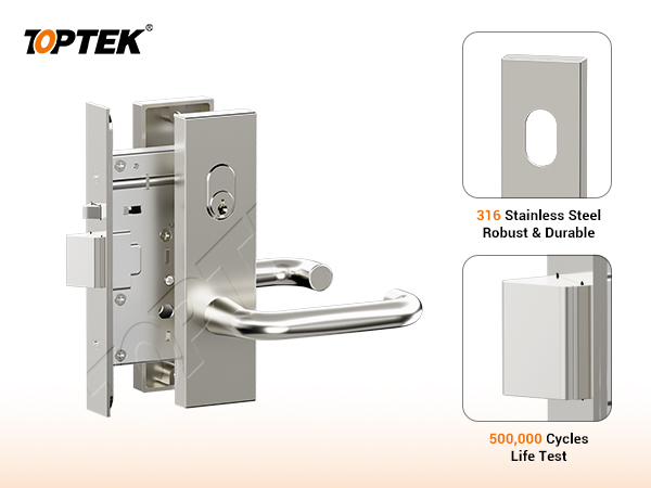
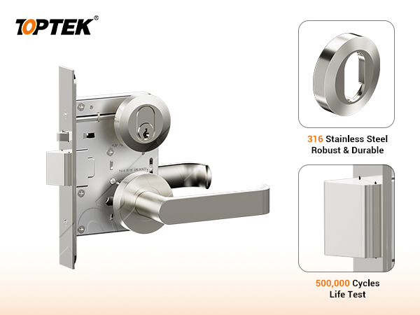
TOPTEK identifies TKAU6400EC as a wide-plate presentation and TKAU6400RR as a sectional or round-rose presentation. The function decision must be coordinated with the selected trim, spindle engagement, fixing and prepared holes. Visit the AS 4145 mortise lock hub for the product-family context.
Yesterday’s backset guide addressed 60, 89 and 127 mm location choices. This article does not repeat that intent: it focuses on side control and handing. Nevertheless, the final approval drawing must contain both function and geometry, because a correctly directed lock still cannot fit an incompatible preparation.
Buyer checklist before configuration
- Mark Side A and Side B on a plan or elevation.
- Identify secure, public, egress or room-side intent.
- State door swing and hinge position from the agreed view.
- Name mechanical, motor or solenoid version.
- Define lever, key, turn and access-control behaviour by state.
- Identify trim, spindle, cylinder and fixing references.
- Confirm who may perform any field setting and how it is recorded.
Common mistakes and project risks
The first mistake is relying on left/right language without a reference view. The second is assuming that a field-selectable feature eliminates configuration control. If site teams can change a setting but no record follows the door schedule, identical openings may behave differently.
Another mistake is treating a lever reversal as a complete handing reversal. Latch orientation, trim, cylinder, cable routes or door preparation may still require review. Never experiment on a life-safety or access-controlled opening. Follow the approved procedure and involve the responsible installer or systems team.
TOPTEK evidence and product scope
TOPTEK’s internal Australian mortice lock material identifies TKAU6400 family configurations and states that lever direction and certain control directions can be changed through product settings. It also distinguishes mechanical, motor and solenoid versions. These statements support a controlled configuration discussion, not a universal claim for every model or doorset.
Request current model drawings and instructions through TOPTEK resources. The current draft does not extend internal tests, customer fire tests or materials statements to a specific order. Those claims require the applicable original report, configuration and documentation review.
Product presentation and approval sample
The TKAU6400EC escutcheon reference and TKAU6400RR round-rose reference help buyers compare presentation. The sample still needs a configuration label stating version, door view, side logic and revision.
Demonstrate every state from the approved table. Photograph the sample from both faces and the edge. If a switch or slider is used, record its approved position without publishing sensitive service instructions. Seal or label settings as required by the project’s quality process.
RFQ checklist for function direction
- Opening number and marked floor-plan detail
- Side A/Side B and hinge reference
- Required operation in every applicable state
- Mechanical, motor or solenoid version
- Trim, cylinder, spindle and fixing references
- Backset and complete door-preparation drawing
- Electrical/control information where applicable
- Sample setting, approval owner and production label
Why TOPTEK: preserve the intended setup
A supplier can add value by translating the buyer’s marked plan into a configuration record. TOPTEK can review side definitions, version, trim and stated operating sequence, then identify missing or contradictory information before quotation.
The same record should appear on the drawing, sample and order acknowledgment. Production and site inspection can then compare actual behaviour with the approved sequence rather than interpreting a verbal left/right instruction.
Two-level CTA
For an initial review, send a marked plan, door swing, photographs and a plain-language description of which side should be controlled. TOPTEK can return the required configuration questions without assuming a setting.
For a formal RFQ, submit the opening schedule, version, state table, door preparation, evidence requirements and sample procedure via the TOPTEK contact page. Request a revision-controlled configuration sheet with the quotation.
Conclusion
Reversibility is useful only when the approved direction is unambiguous. Define the two sides, separate handing from function, name the lock version and show each operating state.
Confirm the exact model procedure and interfaces, demonstrate the sequence on an identified sample and preserve the setting through production and installation. This creates a traceable Australian mortice lock configuration without turning a family capability into an unsupported universal claim.
Frequently asked questions
Is lock handing the same as function direction?
No. Handing describes swing and hinge orientation; function direction describes which side is controlled and how each operator behaves.
Can every TKAU lock be reversed on site?
Do not assume so. TOPTEK family information describes selectable features in certain configurations; confirm the exact model and approved procedure.
Why should buyers use Side A and Side B?
They remove ambiguity when different teams use inside, outside, left and right from different viewpoints.
Does a reversible lever prove the lock function is reversible?
No. Lever orientation is only one interface. The latch, internal function, trim, cylinder, cabling and preparation may require separate confirmation.
What belongs on the sample label?
Include opening number, exact version, reference view, side logic, trim, drawing revision and the approved setting status.