

Australian Mechanical vs Motor vs Solenoid Mortice Lock: RFQ Selection Guide
TL;DR
Use the mechanical version when locking is created by mechanical keys, turns or lever logic; use the motor version only when the approved electronic lock design calls for motor-driven actuation; use the solenoid version when the access-control design specifies a solenoid-controlled state. For every powered version, define voltage and current from the current drawing, fail-safe/fail-secure or project-specific power-loss behaviour, monitoring, cabling and emergency egress before quotation.
Start with the AS 4145 Mortise Lock product hub, then use this narrower guide to define the required function and approval evidence.
Quick Answer
Do not ask simply for an “electronic mortice lock.” Send a state table covering normal power, authorised access, locked state, inside egress, fire/alarm input where applicable and power loss. TOPTEK’s Australian source distinguishes mechanical, motor and solenoid families, but the exact electrical values and behaviour must come from the current configuration drawing.
Why version names are not enough
Mechanical, motor and solenoid describe different ways a lock state may be controlled. They do not by themselves define who can enter, what the levers do, how the bolt moves, what happens on power loss or which monitoring contacts are supplied.
TOPTEK’s Australian product material distinguishes a mechanical version for mechanical locking, a motor version for electronic locking and a solenoid version for access-control systems. Use those as family boundaries, then obtain exact configuration data before quotation and approval.
When a mechanical version fits
A mechanical lockcase is appropriate when the required states are produced by mechanical components such as keys, cylinders, turns, buttons or lever logic. It avoids electrical interfaces, but still requires a complete operating sequence.
State outside access, inside egress, deadbolt or latch behaviour, cylinder format, trim and keying. Mechanical does not mean generic: two lockcases can share an appearance while providing different functions or preparation. Approve the identified case and trim together.
When a motor version enters the design
A motor version should enter the RFQ only when the approved electronic lock or access design calls for motor-driven actuation. The RFQ must define what the motor changes, how long actuation takes where relevant, and what mechanical operation remains available.
Do not invent voltage, current, duty cycle or monitoring from a family description. Request those values from the current model drawing and datasheet. Coordinate the controller, power supply, cable path, door loop or transfer device and commissioning responsibility.
When a solenoid version enters the design
A solenoid version is associated with an access-control system that energises or de-energises a controlled lock state. The project must define whether the intended configuration is fail-safe, fail-secure or another documented behaviour and what the inside lever does in every state.
The words “solenoid lock” do not settle fire, egress or security responsibilities. Provide the access-control sequence, alarm or release inputs where applicable, power-loss state, manual override, monitoring outputs and responsible designer approval. Use only model-specific electrical values.
| Decision | Mechanical | Motor | Solenoid |
|---|---|---|---|
| Control source | Key/turn/lever logic | Motor-driven actuation | Energised/de-energised state |
| Essential RFQ input | Function and keying | State table plus model electrical data | State table, fail state and model electrical data |
| System interface | Mechanical hardware | Controller, power, cabling | Controller/relay, power, cabling |
| Approval focus | All mechanical states | All powered, loss-of-power and override states | All energised, de-energised and override states |
| Do not assume | One mechanical function fits all | Generic motor values | Generic fail-safe/fail-secure behaviour |
Build a state table before selecting hardware
List normal powered state, authorised credential, locked state, inside operation, mechanical override, fire/alarm input where applicable and loss of power. Describe what the latch, deadbolt and each lever do.
A state table reveals contradictions early. For example, a buyer may request fail-secure outside access but also expect an undefined automatic release. The responsible project team must resolve the conflict; the supplier should not guess. Attach the approved state table to the quotation and sample record.
Coordinate the access-control ecosystem
Powered mortice locks are only one part of a system. Coordinate reader, controller, power supply, relay logic, door position monitoring, request-to-exit, cable transfer and any interface to fire or building systems.
Keep responsibilities explicit. The lock supplier can provide model data and samples, while the system designer determines the approved sequence and integration. A successful bench test does not approve the complete installed opening or building system.
Buyer checklist before requesting a version
- Opening number and door application
- Mechanical, motor or solenoid family request
- Plain-language inside and outside states
- Latch/deadbolt and lever behaviour
- Power-loss and emergency state where applicable
- Model-specific voltage/current/data request
- Monitoring and control interfaces
- Cable path and door power-transfer plan
- Cylinder or mechanical override requirements
- Door/strike preparation and trim
- Evidence scope and responsible reviewer
- Identified sample and commissioning plan
Common mistakes and project risks
One mistake is using “electric lock” as a complete specification. Another is transferring electrical data from a different model. A third is approving normal powered operation without testing power loss, inside egress and mechanical override.
The consequences can include controller incompatibility, insufficient power, overheating, incorrect secure state, cable damage, inaccessible doors or uncontrolled site modifications. Mark unverified fields as open and stop approval when the operating or life-safety sequence remains unclear.
TOPTEK evidence and product scope
TOPTEK’s AS product insight provides the three-version family distinction used here and identifies the TKAU6400 family as the current writing scope. It also describes configurable inside/outside lever control for the family.
Exact electrical ratings, monitoring options, evidence and tested configuration were not established from that source alone. Request current documents through TOPTEK resources. Do not turn internal test statements or image text into third-party certification claims.
Product presentation and physical interfaces
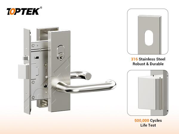
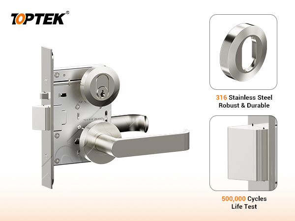
Use the TKAU6400EC escutcheon reference and TKAU6400RR round-rose reference to discuss presentation. Neither page title alone proves the selected mechanical, motor or solenoid internals.
Confirm case version, backset, trim footprint, spindle/cylinder interface, door thickness, hand or function setting, strike, cable entry and connector location. Use an identified sample that matches the drawing and electrical schedule.
RFQ checklist
Include the state table, exact version request, model or approved equivalent, backset, trim, cylinder/override, door and frame preparation, electrical schedule, monitoring, cable transfer, controller/power supply responsibility, evidence list, sample quantity, commissioning tests and revision owner.
Ask TOPTEK to identify every assumption and missing field. The quotation should not replace open data with generic values. Require the drawing, wiring information and sample label to cite the same configuration and revision.
Why TOPTEK: control the interface questions
TOPTEK can review the door schedule and state table before quotation, distinguish mechanical from powered requests and flag missing electrical or physical interfaces. This reduces the chance that a general product family name hides a different operating state.
The team can link the quotation, drawing, sample and production reference. For repeat orders, changes to controller, power supply, fail state, trim or function can be reopened deliberately rather than silently copied.
Two-level CTA
For an initial review, send the opening schedule and a simple state table showing normal, authorised, locked, inside-egress and power-loss behaviour. Mark every unknown instead of guessing.
For a formal RFQ, submit the approved access-control sequence, electrical schedule, door preparation, trim/cylinder data, evidence requirements and commissioning plan through the TOPTEK contact page. Request a configuration-specific drawing.
Conclusion
Mechanical, motor and solenoid mortice lock versions are different control families, not interchangeable labels. Select the family from the approved operating sequence and system architecture, then obtain exact model data.
For powered versions, define the power-loss state, inside egress, override, monitoring, cable path and controller responsibility. Coordinate the physical lockcase and trim as carefully as the electrical interface. Approve an identified sample in every required state and retain the record for production and commissioning.
Frequently asked questions
What is the difference between motor and solenoid mortice locks?
A motor version uses motor-driven actuation, while a solenoid version changes a controlled state through energising or de-energising a solenoid. Exact behaviour is model-specific.
Does solenoid automatically mean fail-safe?
No. The approved configuration must state the power-loss behaviour; do not infer it from the word solenoid.
What electrical values belong in the RFQ?
Use voltage, current, duty, monitoring and wiring data from the current model documentation, not a family description or another model.
Should powered samples be tested without power?
Yes. Test every approved normal, authorised, inside-egress, override and power-loss state relevant to the project.
What should TOPTEK receive?
Send the opening schedule, state table, electrical and interface requirements, preparation, evidence list, sample plan and approval owner.