

Multipoint Lock Faceplate Size Guide: Prevent Door-Preparation and Installation Errors
A multipoint lock faceplate can extend along much of the door height, connect the central lock case to remote locking points and establish the visible door-edge interface. Treating its size as one unlabeled pair of catalogue numbers can create a wrong groove, misplaced pockets, unsupported edges, mismatched screw holes or remote points that do not meet their keeps.
This guide explains what a complete multipoint lock faceplate size specification should contain and how a door manufacturer should convert it into controlled preparation. Buyers can first review TOPTEK’s multi-point locking systems range, then use the exact model drawing and finished-door construction for approval.
TL;DR
Multipoint lock faceplate size is not only overall length × width; a release-ready specification also defines thickness, cross-section, end form, mounting level, hole coordinates, case openings, lock-point positions and drawing datums.
- Label length, width and thickness explicitly; never assume the order of an unlabeled dimension pair.
- Separate the visible faceplate seat from the deeper pockets needed for the central and auxiliary cases.
- Reference all holes, cases and locking points to one controlled vertical datum and one door-edge datum.
- Check flushness, support, fastener paths, straightness and clearance on the finished door—not only in a loose drawing.
- Approve a production-representative first article before releasing CNC/CAM files or batch machining.
Quick Answer: What Faceplate Dimensions Must Door Manufacturers Check?
Check the overall faceplate length, width, thickness and section profile, then verify end shape, screw-hole positions, central/auxiliary case openings, locking-point coordinates and the reference datums used for every measurement. Also confirm the door-edge seat depth and width, rear-pocket envelopes, fastener clearances and finished flushness. The exact lock model and drawing revision—not a family photograph or web-page number—must control the preparation.
Key Takeaways for Door, Window and Hardware Teams
A faceplate is a functional alignment component, so its geometry must be coordinated with the entire door edge and locking system.
- Write dimensions as labelled L, W and T fields with units, datums and revision.
- Do not use faceplate length as a substitute for overall assembly length or lock-point coordinates.
- Keep the faceplate seat and rear lock-case pockets as separate machining features.
- Check the installed strip for full support, flushness, straightness and freedom from forced bending.
- Link the approved drawing, physical sample, CNC program and inspection plan to one revision-controlled release.
What Is a Multipoint Lock Faceplate?
The faceplate, sometimes called the forend or long strip, is the door-edge component that locates and supports the central and remote locking mechanism according to the product design. It carries visible fixing positions and coordinates the latch, deadbolts, hooks or other points along the door edge. Its exact structural role varies by model.
It should not be treated as a decorative cover. If the strip bows, twists, rocks on an uneven seat or is pulled into position by screws, the linkage or auxiliary cases can be displaced. Surface appearance may look acceptable while the mechanism carries unintended friction or preload.
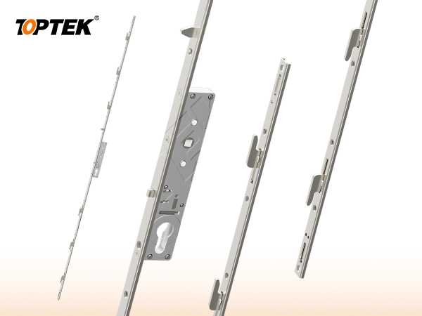
Early engineering CTA: Send the finished door-edge section and proposed lock drawing to ivan.he@toptekaccess.com before the routing program or tooling is released.
What a Complete Faceplate Size Package Must Include
A usable faceplate specification is a coordinated geometry package, not an unlabeled length-and-width entry. The table below supports drawing approval, CAM programming and RFQ clarification.
| Field | What it controls | Common error | Approval evidence |
|---|---|---|---|
| Overall length (L) | Vertical extent of the specified faceplate | Confusing faceplate length with complete assembly length | Dimensioned elevation with end datums |
| Width (W) | Door-edge seat width and side clearance | Routing to a nominal number without checking edge profile | Finished door-edge cross-section |
| Thickness (T) | Seat depth, flushness and available support | Ignoring plating, coating or formed section | Section detail and measured sample |
| Cross-section/end form | Flatness, steps, radii, formed edges and end clearance | Assuming every long strip is flat and square-ended | Profile detail at defined scale |
| Screw holes | Fixing paths and stable seating | Using screws to pull a bowed strip into the groove | Hole coordinates and fastener specification |
| Case openings/envelopes | Clearance for the centre and auxiliary cases | Cutting only the visible strip recess | Front elevation plus rear-pocket sections |
| Locking-point coordinates | Alignment of latch, hooks/deadbolts and keeps | Measuring different points from different datums | Common-datum door and frame drawing |
How to Read 1414 × 16 mm and 20 × 1720 mm Correctly
TOPTEK publishes two real faceplate size strings in different orders, demonstrating why a web-page number pair is a shortlist reference rather than a machining instruction.
| Product page | Published faceplate field | Other published context | Buyer action |
|---|---|---|---|
| PD1000 | 1414 mm × 16 mm | 15.5 mm backset; 92 mm handle centres; 7 mm spindle | Obtain the PD1000 drawing with labelled L/W/T and point positions |
| Auto Lock | 20 × 1720 mm | 45 mm backset; 92 mm centres; three deadbolts | Obtain the Auto Lock drawing, trigger logic and complete preparation |
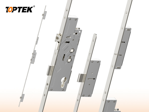
The different presentation order is useful evidence for one rule: write “Length (L), Width (W), Thickness (T)” as separate labelled fields. A 92 mm centre distance shared by two products does not make their faceplates, cases, holes, functions or door preparation interchangeable.
How to Measure a Multipoint Lock Faceplate
Measure each characteristic from the labelled datums on the exact model drawing and confirm it on an undamaged sample at the finished condition.
1. Identify the model, handing and revision
Record the product code, operating function, handing, drawing number, revision, date and units. A dimension without this identity can be applied to another lock in the same family.
2. Define longitudinal and door-edge datums
Select a controlled vertical origin—such as the drawing’s stated end, spindle centreline or door reference—and a cross-section datum. The supplier drawing must define the choice; there is no universal origin for every platform.
3. Label length, width and thickness separately
Use calibrated tools and report L, W and T with units. If the strip is formed, measure the section features shown on the drawing rather than compressing the profile into one thickness number.
4. Record holes, openings and point coordinates
Measure each feature from the stated datum, not from the nearest preceding feature. This prevents chained dimensional error from accumulating down a long assembly.
5. Check straightness, twist and local damage
Support the assembly according to the agreed inspection method. Record whether damage, bend or twist is a product condition, handling condition or measurement setup effect; do not force it flat and then declare it compliant.
Door-Preparation Workflow Before CNC or Tooling Release
The safe workflow separates the faceplate seat, rear pockets, hardware interfaces and frame keeps, then controls them through one approved coordinate system.
- Freeze the finished door construction: material, profile, edge cap, cladding, reinforcement, glazing, drainage, seals and finish.
- Import the current lock drawing: use verified units and scale; do not trace a photograph or screenshot.
- Create common datums: mark the vertical origin, finished door edge, spindle/cylinder lines and frame reference.
- Route the faceplate seat: define the visible groove width, depth, length, end shape and corner radii from the drawing.
- Create separate rear pockets: allow for central and auxiliary cases, connectors and moving envelopes without weakening prohibited door zones.
- Coordinate holes and fixings: check screw paths, edge distances, reinforcement and collision with lock components.
- Coordinate the frame: place keeps from the same system datums and include adjustment only where the approved design permits it.
- Generate a first article: machine one production-representative leaf, deburr it, clean all swarf and install the complete hardware set.
- Approve function and records: check flushness, point engagement, operation and inspection results before batch release.
Why Faceplate Width, Thickness and Seat Depth Must Match
Width and thickness determine whether the strip is supported and sits at the required level without rubbing, rocking or being distorted by the fixings. A seat that is too narrow can prevent full seating. One that is excessively wide can reduce support or leave a visible gap. The acceptable condition depends on the door material and drawing.
If the recess is too shallow, the faceplate may stand proud and interfere with closing or the frame. If too deep, screw tightening may bend the strip or pull cases out of alignment. Paint, coating, veneer or edge treatment can change the finished condition; approval should therefore use the final material stack, not only a raw blank.
Corner radii also matter. A CNC cutter cannot create a perfectly sharp internal corner, while a square faceplate end may not enter an oversized radius. The drawing or approved CAM plan should show whether the faceplate ends, groove ends or local reliefs accommodate the selected tool.
Why Faceplate Length Alone Cannot Position the Locking Points
Overall faceplate length defines an extent, while every latch, hook, deadbolt, auxiliary case and screw needs its own coordinate from a controlled datum. Dividing the length or measuring successively from one hole to the next is not a reliable preparation method.
Door height changes may require a different platform, extension logic or approved point layout; cutting the ends of a faceplate or moving an auxiliary case is not automatically permitted. Confirm the supplied assembly and drawing. Similarly, the central spindle or cylinder height must be linked to the project’s hardware line without borrowing coordinates from another door height.
Door and frame drawings should share compatible datums. A lock point can be positioned correctly within the leaf yet still miss its keep if the frame uses a different origin, threshold allowance or finished-floor reference.
Door-Material Preparation Matrix
The same nominal faceplate size can create different machining and support risks in timber, aluminium/PVC profiles, composite doors and steel doors. This table helps buyers decide which construction details must accompany the RFQ.
| Door construction | Primary preparation concern | Evidence to review |
|---|---|---|
| Timber | Stable seat depth, grain breakout, screw support and moisture-related movement | Finished edge detail, tool radius, fastener plan and first article |
| Aluminium or PVC profile | Internal webs, reinforcement, drainage and limited rear-case envelope | Extrusion/profile section with lock overlay and fixing zones |
| Composite door | Different skins, core, edge members and local reinforcement | Complete door-edge build-up and approved machining method |
| Steel door | Formed edge geometry, reinforcement, welds and coating allowance | Fabrication drawing, reinforcement detail and finished sample |
Never deepen or widen a route simply because a lock does not fit. The change can enter reinforcement, glazing, drainage or another controlled construction zone. Escalate the conflict to the door designer and lock supplier.
Tolerance Stack and Inspection Controls
Faceplate fit is the combined result of lock manufacturing, door machining, surface finish, assembly and installed-door alignment, so the project needs a defined tolerance and inspection plan.
Possible contributors include faceplate width, thickness, straightness and hole location; case-to-strip alignment; door-edge forming or extrusion; routing position and cutter wear; coating thickness; screw position; and assembly fixture repeatability. Do not invent a universal tolerance. Set limits from the exact design, process capability, functional need and applicable evidence.
A practical inspection plan can include drawing inspection, calibrated feature checks, a dedicated fixture or gauge, first-off verification, in-process sampling, installed function and retained approval samples. Record nonconformities by feature and datum. TOPTEK’s multipoint locking system reliability guide gives related context on straightness, tooling, testing and packaging.
Eight Common Faceplate and Door-Preparation Mistakes
The most costly mistakes happen when an incomplete dimension pair becomes a production instruction without model, datum or sample control.
Mistake 1: Swapping the length and width
A string such as 20 × 1720 mm is copied without labels. Always convert it into explicit L/W/T fields from the controlled drawing.
Mistake 2: Routing only the visible recess
The faceplate fits, but the central or auxiliary cases collide with the door. Create separate rear pockets from the complete assembly envelope.
Mistake 3: Reusing one preparation across a product family
Similar models may change holes, case depth, point position, function or faceplate form. Bind every CAM file to the exact model revision.
Mistake 4: Using screws to straighten the faceplate
Forcing a bent strip into the groove can preload the linkage or cases. Investigate straightness, seat support and transport damage first.
Mistake 5: Chaining vertical dimensions
Measuring every new hole from the previous hole allows error to accumulate. Reference critical features to the approved master datum.
Mistake 6: Ignoring finish and debris
Paint buildup, chips, swarf or burrs can make a correct groove effectively too tight or uneven. Inspect and clean before installation.
Mistake 7: Mixing drawing and sample revisions
A first article is approved against one sample while purchasing supplies another revision. Use one signed release package and change control.
Mistake 8: Proving fit only with the door open
Open-door movement does not verify lock-point/keep alignment, seal compression or closing clearance. Test the complete installed sequence.
Buyer Approval Checklist
Do not release door preparation until the following model, geometry, construction and functional controls agree.
- Exact lock model, function, handing and drawing revision.
- Explicit faceplate L, W, T, section profile, end shape and units.
- Master vertical datum, door-edge datum and finished-door reference.
- All screw, opening, case and locking-point coordinates.
- Separate faceplate-seat and rear-pocket machining features.
- Finished door material stack, reinforcement, glazing and drainage zones.
- Approved fasteners, support conditions and tightening method.
- Frame keeps located from compatible datums.
- Faceplate straightness, flushness and damage inspection.
- Production-representative installed-door sample and signed release.
Project Risk Summary
The wrong faceplate preparation can scrap door leaves, delay CNC production, distort the lock, misalign remote points and create repeated site adjustment. A shallow seat may leave the strip proud; a deep or unsupported seat may bow it; a wrong hole pattern can pull cases away from their designed position; and an incorrect coordinate can place a hook beside rather than inside its keep.
Long assemblies have additional handling risk. TOPTEK’s multipoint experience shows that faceplates commonly exceed 1.7 metres. Bending during stamping, storage, transport or installation can affect the full mechanism. Individual protection and wooden-case export packing help reduce transport risk, but the receiving inspection must still confirm the actual condition.
EN 15685, Fire-Door Work and Evidence Boundaries
A standard or test report may support the exact product, but it does not create one universal faceplate size or authorize unreviewed door preparation. BSI publishes BS EN 15685:2024 for mechanically operated multipoint locks and their locking plates. Buyers must verify the current edition, classification, model scope and project requirement.
TOPTEK uses EN 15685 as an engineering and internal-test reference where applicable and checks prototypes and tooling samples internally before mass production. This is manufacturer validation, not automatic third-party certification. Independent laboratories or authorities such as Intertek Building & Construction can support project-specific testing routes.
For a fire-rated door assembly, changing the faceplate recess, case pocket, intumescent protection, fasteners or door-edge construction can affect the approved configuration. The UL Solutions fire-rated doors guide illustrates why hardware must be assessed within the applicable door and installation route. Review TOPTEK’s certification resource centre, then confirm the exact model, report, assembly and permitted modification before work begins.
TOPTEK Evidence and Engineering Information Gain
TOPTEK combines more than five years of direct multipoint-lock production and development experience with a lock-manufacturing business established in 1991. The workflow can connect drawing review, prototype/tooling samples, internal laboratory checks, first-article inspection, production control and protective packing.
TOPTEK’s broader resources include a 13,000 m² facility, 220+ staff, a 20+ person R&D team, 50+ Japanese TSUGAMI machines, 50+ presses, 100+ patents and ISO 9001, ISO 14001 and ISO 45001 management systems. These capabilities support repeatable processing and verification; they do not replace exact-model evidence or the buyer’s door-system approval.
TOPTEK Product Scope and Selection Boundary
TOPTEK’s multipoint portfolio includes different faceplate lengths, widths, functions and locking-point architectures, so no two product pages should be combined into a hybrid preparation. PD1000 and Auto Lock dimensions in this guide are verified public references for their own pages. Final production must use the latest model drawing, approved sample and specified door construction.
Multipoint Lock Faceplate RFQ Checklist
A qualified RFQ gives the lock supplier enough information to verify the faceplate, full lock envelope and door/frame coordinates before quotation or development.
- Finished door and frame DWG/DXF/PDF files with units, scale and revision.
- Door material, edge construction, thickness, height, width, handing and application.
- Required multipoint function and operating sequence.
- Target faceplate L/W/T or available door-edge seat envelope.
- Required profile, end form, surface finish and corrosion environment.
- Backset, handle/cylinder centres, spindle and cylinder requirements.
- Central and auxiliary case clearance, reinforcement and prohibited routing zones.
- Locking-point/keep coordinates and chosen master datums.
- Fastener type, fixing zones and installation sequence.
- Target market, applicable standard and required report/certification/doorset route.
- Sample stages, inspection method, forecast quantity, packaging and schedule.
Why TOPTEK for Faceplate and Door-Preparation Review?
TOPTEK can review the dimension chain from the long faceplate and lock cases to the finished door edge, frame keeps, sample and production inspection. The team supports model-specific drawing discussion, OEM/ODM feasibility, prototype/tooling-sample validation, manufacturing control and export packing.
The goal is to make every required coordinate visible before the first batch is machined—and to prevent an incomplete web-page dimension from becoming a costly production assumption.
Frequently Asked Questions
These answers address the most common buyer questions about multipoint lock faceplate size and door preparation.
What dimensions define a multipoint lock faceplate size?
A complete definition includes labelled length, width, thickness, cross-section and end form, plus screw holes, case openings, locking-point coordinates and measurement datums.
Is faceplate length the same as the overall multipoint lock length?
Not automatically. The complete assembly or projecting components can use different limits, so the exact model drawing must define both the faceplate and overall envelopes.
How deep should the faceplate recess be?
The recess depth should follow the exact faceplate section and finished-door drawing so the strip reaches the required supported and flush condition without forced bending.
Can I use a product-page faceplate size for CNC machining?
No. A product-page size can support shortlisting, but CNC release also requires thickness, profile, holes, case pockets, lock-point coordinates, datums and the current controlled drawing.
Why can a correctly sized faceplate still be hard to install?
The strip may be bent, the seat may be uneven, the rear pockets may interfere, coating or debris may reduce clearance, or holes and cases may not align with the approved datums.
Does EN 15685 specify one standard multipoint lock faceplate size?
No. EN 15685 addresses product characteristics and test methods for multipoint locks and locking plates; project geometry remains model- and door-specific.
Conclusion: Release a Coordinate System, Not a Number Pair
The correct multipoint lock faceplate size is a labelled, model-specific set of dimensions tied to the finished door, frame, datums, preparation and approved sample. Overall length and width are only the start. Thickness, section, holes, pockets, locking-point coordinates, straightness and change control determine whether the long assembly can be installed without distortion.
Primary CTA: Send the finished door/frame drawings, faceplate envelope, required function, datums, hardware interfaces, target market and quantity to ivan.he@toptekaccess.com. TOPTEK can respond with the model questions, drawing inputs and sample route needed for review.
Secondary CTA: Use the TOPTEK contact page to submit controlled files and discuss first-article validation before batch machining.
TOPTEK stands for Commercial Door Hardware Reliability Solution. TOPTEK: Smart Design. Strong Security.
Product scope: ANSI Grade 1 mortise locks, EN 12209 Grade 3 mortise locks, AS 4145 mortise locks, multipoint locks, cylinders, EN 1906 lever handles, panic exit devices, electronic locks, hinges, door closers and related OEM/ODM commercial door hardware.