
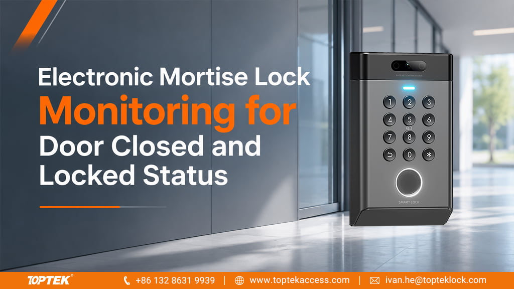

A door can be closed without being locked, and an access controller can send an unlock command without confirming the lock’s physical response. For an integrator buying electronic mortise locks, useful monitoring begins by separating those conditions.
TOPTEK’s electronic-lock range includes self-locking solenoid-controlled models, motorized models and coordinated access-control components. Select the lock for the required entry and exit operation, then specify the feedback needed by the building system. A general request for a monitored lock leaves too much room for different interpretations.
Match each displayed status to a physical condition
| Information | What it can tell the operator | What it does not prove by itself |
|---|---|---|
| Unlock command | The controller issued an output | The lock released or the door opened |
| Door position | The leaf reached the sensor’s defined closed position | The latch or deadbolt engaged |
| Latch or deadbolt feedback | The monitored mechanism reached its defined state | Every other part of the opening is secure |
| Lever or exit event | The specified exit input was operated | The door completed an opening and closing cycle |
The practical consequence is that a single green indicator labelled “secure” can conceal missing information. If a project needs confirmation of both closure and locking, the system designer should define those conditions separately and decide how the controller combines them.
This distinction is also reflected in SDC’s door-position sensor guidance, which describes door position and lock-status monitoring as complementary functions. It is a useful design principle, not a statement that SDC components have been validated with a particular TOPTEK lock.
Start with the actual TOPTEK lock function
For example, TKEUS3592 is a conventional-latch self-locking platform, while TKEUSC3592 is its cross-latch counterpart in the product range. TOPTEK’s functional description separates electrical authorization for outside lever operation from inside mechanical opening. That operating sequence is the starting point for deciding which events the controller needs to observe.
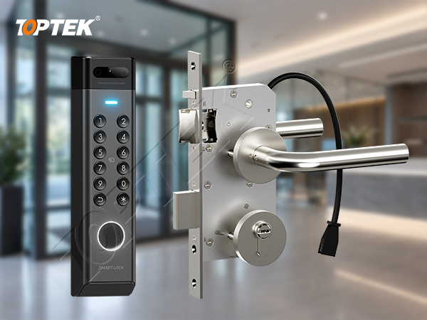
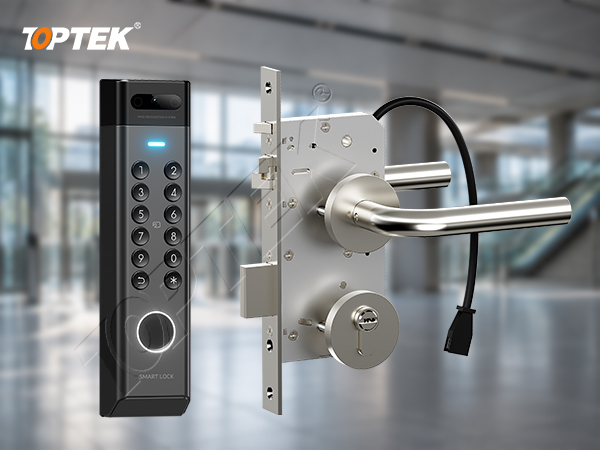
The wider self-locking family includes options for feedback from mechanisms such as the deadbolt, latch, lever, trigger and cylinder. Specify the required points on the quoted configuration; the family list does not mean every model includes five outputs. The applicable wiring diagram should identify each available signal and its electrical interface. Request it through the TOPTEK product documentation resources with the exact model reference.
Define the useful exception before adding more signals
Consider an office entrance whose door-position contact reports closed but whose required locking feedback has not changed. The building team needs a clear exception to investigate, rather than an automatically reassuring “secure” label. The cause could involve incomplete latching, alignment, a contact condition or input mapping; the status combination identifies the condition, not the root cause.
For a door held open after valid entry, the useful observation may instead be that the door-position signal remains open after the project’s permitted interval. Adding a cylinder event does not answer that question. Choose feedback according to the operational decision it supports, then set timing and alarm behaviour within the controller’s approved design.
This keeps procurement focused. Buyers pay for the lock configuration, wiring and integration they need, and the handover explains what operators should do when the reported state changes. More signals are useful only when their meaning is understood.
Coordinate the feedback path with the lock order
TOPTEK’s electronic engineering capability supports discussion of the lock and access-control arrangement together. Provide the controller’s input requirements and the status conditions you need. The response should identify which points come from the lock, which require another device, and the wiring information for the proposed configuration.
Power and feedback may share the route between frame and moving leaf, but they are separate circuit requirements. An electric door loop protects the cable path; it does not determine signal availability or electrical capacity. Allocate conductors and connections from the selected components’ wiring requirements rather than from the appearance of a cable or connector.
On the representative door, compare the physical condition, controller input and displayed message during normal closing, authorized entry and the relevant exception conditions. Use the electronic mortise lock commissioning guide for the broader acceptance sequence. Keep any life-safety or fire-door requirements tied to the approved opening design and product scope.
Request a monitoring configuration response
Send TOPTEK the preferred lock model, controller model or input specification, and a short list of conditions that operators must distinguish. Include one door drawing and the required sample quantity. Through the TOPTEK enquiry form, request a configuration quotation identifying the available feedback points, matching wiring information and sample arrangement.
The electronic lock and access-control range provides the product starting point. Review the quotation against the intended status meanings before ordering the door wiring, so the installation supports the monitoring function the buyer expects.
Frequently asked questions
Does door closed mean the mortise lock is locked?
No. Door position and locking feedback describe different physical conditions. Define the required combination for the selected lock and controller.
Does every TOPTEK self-locking model include five monitoring outputs?
No. Monitoring options vary by configuration. The quotation and applicable wiring diagram must identify the points supplied for the selected model.