

CE Mortise Lock Replacement Guide: How to Measure an Existing Door Preparation
Focus: CE mortise lock replacement measurements
Author: Ivan He, TOPTEK | Technical review status: final engineering sign-off required before publication.
TL;DR
- Do not order a replacement from one number, an old catalogue name or a front-view photo.
- Survey the opening as a system: door, pocket, lock case, forend, spindle, cylinder or keyhole, trim, strike, frame and function.
- Measure backset and centre distance from clearly identified reference lines; photograph the tape or caliper position.
- Remove the old lock when possible and measure both the component and the preparation. Wear, filler and site alterations can make them different.
- For fire or smoke doors, treat substitution as a technical approval decision. A CE-marked component is not automatic permission to enlarge, patch or change the tested door preparation.
Quick Answer
The essential CE mortise lock replacement measurements are: function, door thickness, handing, backset, lever-to-cylinder or keyhole centre distance, lock-case height and depth, forend length, width, thickness and end shape, fixing-hole positions, follower square, cylinder or keyhole format, latch and deadbolt positions and projection, strike geometry, and the actual pocket size. Record every dimension against a labelled datum and approve a production-intent sample in the existing opening before quantity release.
Replacement Is a Measurement-and-Function Match
A replacement project starts with an existing hole, but the hole is not the specification. A worn lock may have been forced into an oversized pocket, the strike may have been filed, decorative trim may hide abandoned holes, and the function may no longer match the original hardware schedule. The buyer’s job is to capture the present condition and recover the design intent before choosing a new lock.
This guide is deliberately different from general CE selection, case-depth, forend/strike and cylinder/spindle guides. Its search intent is field surveying: how to create enough reliable evidence for a supplier to propose a replacement without guessing.
1. Prepare the Survey Before Removing Hardware
Use a steel rule, tape, vernier caliper, square, depth gauge or depth rod, marker labels and a camera. Add a simple sketch with one horizontal and one vertical datum. Give the opening an ID that matches the door schedule. Photograph the complete door from both sides, the door edge, frame, strike and all visible markings before disassembly.
Record the door condition
- Door and frame material, finished door thickness and edge construction
- Handing, swing direction, door bevel and closing direction
- Single or paired door, including astragal or meeting-stile conditions
- Fire/smoke label, seals, intumescent protection and closer arrangement
- Signs of sag, rubbing, loose hinges, distorted edge, filler or previous repairs
If the opening is fire rated or controls escape, confirm the temporary safety plan before removing hardware. Do not leave the opening unsecured or alter the preparation merely to obtain a measurement.
2. Measure in a Controlled Sequence
| Sequence | Measurement or evidence | Why it controls replacement |
|---|---|---|
| 1 | Function and operating states | A physically fitting lock can still provide the wrong locking or egress behavior. |
| 2 | Door thickness, handing and trim stack | Controls spindle, cylinder, fasteners, bevel orientation and interface position. |
| 3 | Backset and centre distance | Locates lever, cylinder/keyhole and visible trim holes. |
| 4 | Case envelope and pocket | Shows whether the new body fits without weakening or enlarging the door. |
| 5 | Forend and fixing pattern | Controls the visible recess, edge coverage and secure attachment. |
| 6 | Follower, cylinder and trim interfaces | Prevents mismatched spindle, cam, projection and through-bolt conflicts. |
| 7 | Latch, deadbolt and strike relationship | Determines closing, latching, locking and frame preparation. |
| 8 | Markings and evidence | Supports model traceability and fire-door substitution review. |
3. Identify Function Before Dimensions
Write what each input does from both sides in the locked and unlocked states. Does the lever retract only the latch? Does the cylinder operate the deadbolt, the latch and deadbolt, or only release an outside lever? Is there a bathroom turn and emergency release? Is the door passage-only, classroom, night-latch, deadbolt, roller-latch or escape-related?
Do not identify function from the shape of the case alone. TOPTEK’s current EN 12209 range includes separate sash, passage, deadbolt, night-latch, classroom, roller, bathroom and escape-related models. Function changes can alter internal operation even when a centre distance appears familiar.
4. Take the Critical Lock and Door Measurements
Backset
Backset is the horizontal distance from the specified door-edge or forend datum to an operating axis. In a field report, label whether you measured to the lever follower, cylinder centre or another axis. Do not hide this definition behind a single number. TOPTEK’s published EN72SL data lists backset options from 40 to 100 mm; that range is product-family information, not proof that one option matches the existing cut-out.
Centre distance or PZ
Measure vertically from the centre of the follower to the centre of the Euro profile cylinder, keyhole or turn axis. TOPTEK EN72SL is a 72 mm-centre platform, but 72 mm does not define the backset, function, follower size or case envelope. Use centre-to-centre measurement rather than edges of worn holes.
Case envelope and pocket
With the lock removed, record body height, depth and thickness; also record projections, screw bosses and moving parts that require clearance. Then measure the actual pocket at the top, middle and bottom. Note depth, width, height, stepped recesses, reinforcement and any wires. The pocket must not force the lock sideways or leave it unsupported.
Forend
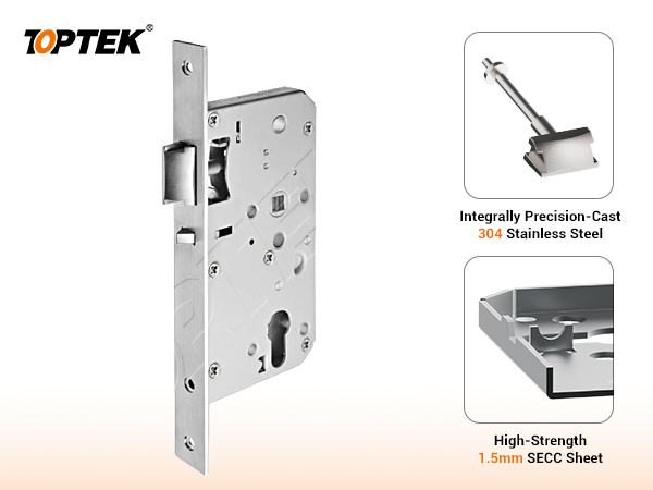
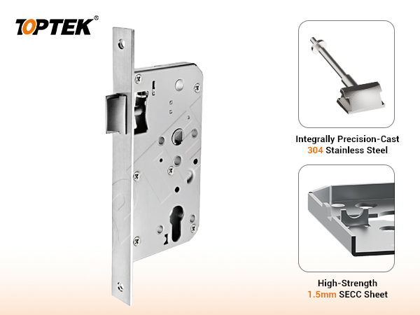
Measure overall length, width, thickness, corner radius or square ends, fixing-hole centres and the vertical locations of latch and deadbolt openings. Record whether the plate is flush, proud or recessed. The EN72SL public data lists a 235 mm-high, 3 mm-thick forend with 20, 22, 23 or 24 mm widths and round or square options; the exact candidate still requires a controlled drawing.
Follower, cylinder and keyhole
Measure follower square and its depth or spindle engagement. Identify the cylinder profile, fixing-screw position, cam and A/B length, or document the old keyhole shape if it is not a profile-cylinder lock. Measure visible trim and through-bolt holes from the same datums. The EN72SL page lists 8 x 8 mm and 9 x 9 mm follower options; never assume which is installed.
Latch, deadbolt and strike
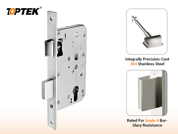
Measure latch and deadbolt centre lines relative to the forend, bolt size and projection, latch bevel direction and deadbolt throw sequence. On the frame, record strike length, width, thickness, lip, fixing pattern, box depth and location relative to the door’s installed centre lines. Photograph wear marks: they often reveal sag or misalignment that a new lock alone will not correct.
5. Replacement Measurement Sheet
| Field | Existing component | Door/frame preparation | Candidate requirement |
|---|---|---|---|
| Function | State-by-state operation | Required access/egress | Exact function code |
| Backset | Datum to axis | Existing trim-hole axis | Same reference and tolerance |
| Centres/PZ | Follower to cylinder/keyhole | Door-face hole centres | Overlay match |
| Case | Height, depth, thickness | Pocket at three positions | Fits without unapproved enlargement |
| Forend | L × W × T, ends, holes | Edge recess and condition | Flush cover and secure fixing |
| Interfaces | Follower, cylinder, spindle | Trim and through-holes | Matched component package |
| Strike | Plate, lip and apertures | Frame recess and centre line | Stable latch/deadbolt engagement |
Add tolerance, measuring tool, surveyor, date and photo reference to every critical row. Where the old part is badly worn, state that the recorded value is observational and must not be treated as the nominal design dimension.
6. Common Replacement Mistakes
- Choosing from backset alone and discovering that the PZ, forend or function is different.
- Measuring to the edge of a worn follower or cylinder hole instead of its centre.
- Recording the removed lock but not the oversized or altered door pocket.
- Ignoring escutcheon footprints and abandoned through-holes that remain visible.
- Copying the old strike position even when hinge wear or door sag caused the misalignment.
- Assuming left/right handing without recording latch bevel and door swing.
- Replacing a fire-door lock solely because the new component carries CE marking.
7. Project Risks and Release Controls
| Risk | Hold point | Required evidence |
|---|---|---|
| New case does not fit the pocket | No cutting until overlay review | Old lock, pocket and candidate drawings |
| Trim holes remain exposed | No cosmetic approval from lock-only sample | Both door-face overlays and assembled sample |
| Wrong function or egress behavior | No quantity release from dimensions alone | Signed operation matrix on fitted opening |
| Latch or deadbolt binds at strike | Correct door geometry before filing parts | Gap, hinge, seal and strike inspection record |
| Fire-door evidence gap | No substitution approval from catalogue claim | Applicable door-set evidence and technical acceptance |
8. TOPTEK Evidence and Product Range
TOPTEK’s Intertek certificate 2649-CPR-26002201 covers listed mechanically operated mortice locks and latches under EN 12209:2003/AC:2005 for fire-resistance and/or smoke-control door use within its stated scope. The certificate was first issued on 4 June 2026 and shows 31 December 2026 as its expiry date, subject to its validity conditions. Replacement approval must trace the proposed model and function to current applicable documents; it must not transfer one model’s classification to another.
For orientation, compare the EN 12209 mortise lock hub, EN72SL sash lock and EN72LL passage lock. Use the existing EN 12209 buyer guide, certification resource page and laboratory capability page for supporting context. Public pages guide selection; the approved model-specific drawing controls manufacture and preparation.
9. RFQ Checklist for an Existing Opening
- Opening ID, quantity and replacement programme schedule
- Door/frame material, finished thickness, handing, swing and bevel
- Fire/smoke/escape status and available labels or evidence
- Existing lock markings, model, function and operating-state description
- Backset and centre distance with labelled reference datums
- Case height, depth, thickness and actual pocket envelope
- Forend L × W × T, end shape, hole centres and recess condition
- Follower square, spindle, cylinder/keyhole and trim-hole pattern
- Latch/deadbolt size, locations, projections and strike geometry
- Photos with scale, dimensioned sketch and old-lock sample where available
- Required finish, package contents, sample quantity and approval tests
- Golden sample, drawing revision and deviation-control process
Why TOPTEK
TOPTEK can review the survey as a coordinated replacement package: lock function, critical dimensions, cylinder and spindle interfaces, strike, model scope, sample build and production controls. The value is a documented comparison between the existing opening and the proposed configuration—not a promise that a catalogue family is universally interchangeable. TOPTEK’s internal laboratory supports development and consistency checks; internal checks are not presented as third-party certification.
Frequently Asked Questions
What are the minimum CE mortise lock replacement measurements?
Record the function, door thickness, backset, lever-to-cylinder or keyhole centre distance, case height and depth, forend length, width, thickness and end shape, follower square, cylinder or keyhole format, fixing positions, latch and deadbolt geometry, strike position and handing.
Can I select a replacement mortise lock from the backset alone?
No. Two locks can share a backset but differ in centre distance, case envelope, forend, function, spindle, cylinder interface, strike geometry and certification scope.
Where should the backset be measured from?
Use the controlled drawing definition. For a field survey, measure from the finished door-edge or forend reference line to the centre of the lever follower and, where relevant, the cylinder axis. State the reference used and include a photo.
Should the old mortise lock be removed before measuring?
Yes, when the opening can be safely taken out of service. Measure the removed lock and the door pocket separately, because paint, filler, deformation or an oversized pocket can hide the original preparation.
Can an old fire-door mortise lock be replaced with any CE-marked lock?
No. The replacement must be reviewed against the applicable door-set evidence, lock model and function, preparation limits, compatible hardware and installation instructions. A CE mark alone does not approve every substitution.
What should be included in a replacement lock RFQ?
Include a dimensioned survey sheet, door and frame photos, removed-lock photos, function description, door material and thickness, handing, fire or smoke requirement, quantities, existing markings, required finish and a production-intent sample approval plan.
Conclusion
Reliable replacement starts by converting an altered opening into controlled data. Measure the old lock and the preparation, identify function before selecting a case, compare every interface on one overlay, and test one complete opening before releasing quantity. This prevents the predictable failures: exposed holes, an unsupported case, wrong lever or cylinder positions, strike binding, incorrect function and unsupported fire-door substitution.