

ANSI Mortise Lock Door Preparation Checklist: 10 Dimensions Door Factories Must Confirm
TL;DR
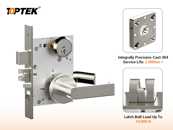
ANSI mortise lock door preparation should never begin from the backset alone. Before machining a commercial door, confirm the door construction, thickness, backset, lever-to-cylinder centres, lockcase pocket, armour faceplate, trim holes, spindle and cylinder projection, strike preparation, handing, bevel, function and template revision. For TOPTEK’s current TKAM9200 platform, useful catalogue reference points include a 2-3/4 in (70 mm) backset, 3-5/8 in (92 mm) lever-to-cylinder centre distance, and a standard 1-3/4 in (44.5 mm) door thickness. These values do not replace the controlled drawing for the exact lock function and trim ordered.
Quick Answer
What must a door factory confirm before preparing a door for an ANSI mortise lock? Confirm the exact lock model, function, trim style, door material, door thickness, backset, vertical and horizontal centre lines, pocket envelope, faceplate recess, through-hole pattern, cylinder and spindle requirements, strike position, handing, bevel and drawing revision. The safest workflow is to freeze the hardware schedule, obtain the manufacturer’s model-specific template, overlay it on the door and frame drawings, and approve one revision before cutting.
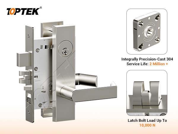
TOPTEK’s ANSI Grade 1 mortise lock range includes round-rose and escutcheon trim configurations. They may share a lock platform, but their visible trim and fixing patterns are not interchangeable door-preparation assumptions.
Key Takeaways for Door Factories and Contractors
- A nominal “ANSI mortise prep” is a starting convention, not permission to cut every lock and trim combination from one generic template.
- Backset and lever-to-cylinder centres locate the operating geometry; they do not define the complete pocket, faceplate, trim or strike preparation.
- Wood, composite and hollow-metal doors need different reinforcement and machining decisions, even when the visible centre lines are similar.
- The strike centre line must be coordinated with the lock centre line after allowances for door bevel, clearances, seals, hinges and frame condition.
- The current manufacturer drawing for the ordered model, function and trim must control production.
The 10-Point ANSI Mortise Lock Door Preparation Checklist
The following checklist is designed for commercial wood-door and hollow-metal-door factories, production engineers, hardware coordinators and site installers. Use it during drawing review, first-article inspection and pre-installation verification.
| Check | What to confirm | Risk if omitted |
|---|---|---|
| 1. Door construction | Wood, composite, hollow metal, stile width, core and reinforcement | Weak fixing, pocket breakout or conflict with internal components |
| 2. Door thickness | Finished thickness, skins, facings and any project tolerance | Wrong spindle, cylinder, screw or trim projection |
| 3. Backset | Finished door edge to lever/spindle centre line | Incorrect lever location or insufficient stile clearance |
| 4. Lever-to-cylinder centres | Vertical distance between operating hub and cylinder centre | Trim and cylinder holes do not align with the lockcase |
| 5. Lockcase pocket | Height, depth, width, corner treatment and installation clearance | Case interference, over-routing or reduced door strength |
| 6. Armour faceplate | Length, width, recess depth, screw locations and door-edge bevel | Faceplate sits proud, latch binds or edge is over-machined |
| 7. Trim through-holes | Round-rose or escutcheon pattern, posts, screws and clearances | Visible unused holes or inability to secure the trim |
| 8. Cylinder and spindle | Cylinder type and length, cam, spindle, thumbturn and door-side projections | Function failure, loose trim or cylinder that cannot engage correctly |
| 9. Strike preparation | Strike model, lip, box, frame reinforcement and three-axis alignment | Latch drag, incomplete deadlocking or excessive closing force |
| 10. Handing and revision | Inside/egress side, swing, bevel, lock function and approved template revision | Reversed operation or production built from obsolete data |
Reference Dimensions for the TOPTEK TKAM9200 Platform
The current TOPTEK TKAM9200 catalogue provides the following planning references. They are useful for early coordination, but the released order drawing remains the production authority.
- Standard door thickness: 1-3/4 in (44.5 mm). A thicker door must be declared so that the correct component lengths can be reviewed.
- Backset: 2-3/4 in (70 mm).
- Lever-to-cylinder centre distance: 3-5/8 in (92 mm).
- Armour faceplate: 8 in × 1-1/4 in (203 mm × 31.5 mm).
- Latchbolt throw: 3/4 in (19 mm).
- Deadbolt throw, where the selected function includes a deadbolt: 1 in (25.4 mm).
Do not derive the pocket width, depth or fixing-hole coordinates by scaling a catalogue illustration. Request the dimensional drawing for the exact function and trim. The TKAMRR9200 round-rose lever trim and TKAMEC9200 escutcheon lever trim illustrate why the lockcase reference and trim template must travel together.
How to Review Each Dimension Correctly
1. Door Material, Construction and Available Stile Width
Start with the door, not the lock. Timber, composite-core and hollow-metal doors do not accept the same cutting and fastening method. Confirm the usable stile width and locate glazing channels, edge caps, seams, wires, stiffeners and fire-door components before approving the pocket. For steel doors and frames, the official ANSI/SDI A250.14 hardware-preparation guidance treats lock and strike locations as coordinated dimensions and directs manufacturers to verify the hardware maker’s specifications.
2. Finished Door Thickness
Measure the finished door, including facings or skins that affect trim seating. Thickness changes the required cylinder, spindle, through-bolts and inside-to-outside trim relationship. “Standard door” is not sufficient for an RFQ; state the nominal dimension and tolerance.
3. Backset
Backset is the horizontal distance from the finished door-edge reference to the operating hub or cylinder centre line, as defined by the drawing. For the TKAM9200 reference, it is 2-3/4 in (70 mm). Check that the stile, edge construction and trim footprint leave enough material around the pocket.
4. Lever-to-Cylinder Centre Distance
The TKAM9200 catalogue reference is 3-5/8 in (92 mm). It controls the lever-hub and cylinder relationship, but function selection still matters. Passage, office and entrance functions may not use the same cylinder, thumbturn or outside-access arrangement. Freeze the function before releasing CNC files.
5. Lockcase Pocket
Review the three-dimensional case envelope, not only a front elevation. Confirm maximum height, depth and thickness; hubs and bosses; cable space if applicable; screw access; and insertion clearance. Allow installation without forcing the case or removing unnecessary door material. Distinguish hardware maximums, machining targets and inspection limits.
6. Armour Faceplate and Door-Edge Recess
The faceplate must sit flush with the finished edge. Confirm length, width, thickness, end shape, screw positions and recess depth. Include the door-edge bevel: a centre line on an unbevelled drawing can shift relative to the frame. Finishes must not fill the recess or obstruct the latch.
7. Round-Rose Versus Escutcheon Through-Holes
Never transfer trim holes from a visually similar product. Round-rose and escutcheon trims can require different posts, through-bolts and clearances. Overlay the exact inside and outside drawings, separate required holes from optional clearances, and mark the outside face before mirroring a CNC program.
8. Cylinder, Thumbturn, Spindle and Fastener Projection
Confirm cylinder format, cam, key side, thumbturn side and effective length. Check spindle engagement without allowing the spindle or screws to bottom out. If door thickness changes after approval, repeat the review; longer screws cannot correct an incompatible cylinder or spindle.
9. Strike and Frame Preparation
The lock may operate correctly on a bench and still fail at the opening because the strike is misplaced. Coordinate vertical centre lines and lateral position after accounting for hinge location, door-to-frame clearances, seals, silencers and expected site adjustment. Verify lip shape, strike box depth, frame reinforcement and fixing method. The current TOPTEK catalogue also warns that a curved-lip strike is not recommended for double doors with overlapping astragals; that condition requires a suitable alternative strike review rather than a site modification guess.
10. Handing, Egress Side, Function and Template Revision
The TKAM9200 lockbody is field reversible, but “reversible” does not eliminate configuration control. The latch orientation and inside/egress side must still match the actual door swing and selected function. Mark the outside/corridor side, hinge side, pull or push direction, bevel and required egress side on the approval drawing. Add the model, trim, function, drawing number, revision and approval date to the CNC record.
Can Wood and Hollow-Metal Doors Use the Same Template?
Not as a complete manufacturing instruction. They can share hardware centre lines when the approved lock calls for them, but the pocket method, edge treatment, reinforcement, fasteners and inspection controls differ. A wood-door factory must protect stile strength and core integrity. A hollow-metal-door factory must coordinate internal reinforcing and make clean, accurately located preparations suitable for the specified fasteners. The ANSI/SDI A250.6 reinforcing guidance is relevant to steel-door construction, while the lock manufacturer’s exact template remains necessary for the ordered hardware.
Common Door Preparation Mistakes
- Approving from backset only. The pocket, trim, faceplate and strike are left unresolved.
- Using an old template because the lock name looks unchanged. The trim, function or revision may have changed.
- Scaling a PDF or catalogue image. Print scaling, image distortion and non-controlling artwork introduce errors.
- Mirroring holes without identifying the outside face. This can reverse asymmetric trim or cylinder preparation.
- Ignoring the door bevel. The latch and strike may not meet at the intended position.
- Preparing the frame separately from the door. Independent centre-line decisions create strike misalignment.
- Changing door thickness after hardware release. Cylinders, spindles and screws may no longer fit.
- Treating field reversibility as a substitute for handing review. The inside/egress side can still be configured incorrectly.
Buyer Checklist Before Approving Production
- Exact lock model and function are shown on the hardware schedule.
- Inside and outside trim codes are confirmed.
- Door material, construction, finished thickness and tolerance are stated.
- Door swing, handing, outside face, bevel and egress side are marked.
- Backset and vertical installation height are coordinated with the door design.
- Lock pocket, faceplate, cylinder, spindle, through-holes and fasteners use one drawing revision.
- Strike model, frame material, reinforcement, box depth and clearances are approved.
- A first-article door has been assembled and function-tested before batch machining.
- Released drawings are stored with the purchase order and inspection record.
ANSI Mortise Lock Door Preparation RFQ Checklist
For a faster and more accurate review, send:
- Target market, project type and estimated quantity.
- Door material, construction, finished thickness and available stile width.
- Door and frame drawings in PDF and, where available, DWG or DXF format.
- Required lock function, cylinder format, keying need and egress requirement.
- Preferred round-rose or escutcheon trim and finish.
- Known backset, installation height, swing, handing and door-edge bevel.
- Strike and frame details, including double-door astragal conditions.
- Required certification or test-document route for the target project.
- Existing lock data, samples or door photos if this is a replacement programme.
If no complete door schedule exists, start with clear photos of the door edge, both faces and frame; basic dimensions; door and frame material; existing lock model; target market; quantity; and any known function or compliance requirement.
TOPTEK Evidence and Verification Boundary
TOPTEK’s current TKAM9200 product catalogue is the source for the platform reference dimensions stated in this article. The public product pages describe the relevant ANSI Grade 1 mortise lock and trim configurations, while the TOPTEK certification and test-document page provides the route for reviewing available evidence. Buyers should request the controlled drawing, current product specification and applicable certificate or report package for the exact ordered configuration.
A public product description, third-party certificate, laboratory report and TOPTEK internal test record serve different purposes. None should be presented as evidence for a door assembly, opening or project condition beyond its stated scope. Door preparation approval must therefore connect the specific lock, trim, function, door construction and project requirements.
Frequently Asked Questions
What is the most important ANSI mortise lock door preparation dimension?
There is no single sufficient dimension. Backset establishes a key centre line, but a usable preparation also needs the lockcase pocket, faceplate, trim holes, cylinder and spindle data, strike location, door thickness and handing information.
Will a 2-3/4 in (70 mm) backset fit every commercial door?
No. It is the TKAM9200 catalogue backset and a common commercial reference, but compatibility depends on the door stile, construction, trim footprint, internal reinforcement and project hardware schedule.
Can a door factory cut from an ANSI standard drawing alone?
No. An industry standard can establish common conventions and dimensional relationships, but the manufacturer’s model-, function- and trim-specific drawing is still required.
Does a field-reversible mortise lock eliminate handing errors?
No. It can simplify stock and assembly, but the latch orientation, inside/egress side, function, door swing and bevel must still be identified and configured correctly.
Why does a lock latch correctly before installation but drag after hanging the door?
Common causes include strike misalignment, incorrect clearances, door sag, seal pressure, an unaccounted door bevel, a faceplate sitting proud, or a pocket that forces the lockcase out of position.
What can TOPTEK return after reviewing our door-preparation files?
Depending on the information supplied, TOPTEK can return a model and trim recommendation, dimensional review comments, missing-data questions, correction points, a sample-validation route, and the appropriate specification or certification-document path for quotation.
Related TOPTEK Technical Resources
Conclusion: Freeze the Preparation Package Before Machining
Reliable ANSI mortise lock installation begins in drawing control. Confirm the ten preparation areas as one package, coordinate the door with the frame, and validate a first article before batch production. The project risk is not limited to a lock that does not fit. Incorrect preparation can create visible rework, weak fixing, latch and strike problems, wrong egress-side operation, delayed door delivery and disputed responsibility between the door, frame and hardware suppliers.