
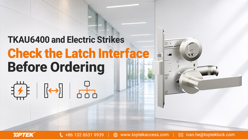

When a system integrator pairs a TKAU6400 mechanical mortice lock with an electric strike, the first decision is mechanical: can the selected keeper receive and release the latch while the auxiliary deadlatch contacts the correct surface? Voltage selection comes after that interface has been established.
TOPTEK’s TKAU6400EC and TKAU6400RR specifications list a 15 mm main latchbolt projection and an 8.5 mm auxiliary deadlatch projection. These are two different components with different jobs. The dimensions are useful inputs for a compatibility enquiry, but they do not identify an approved electric strike by themselves.
Review the main latch and auxiliary deadlatch separately
The main latch enters the keeper area and retains the closed door. The auxiliary deadlatch needs the contact arrangement specified for the lock and strike combination. It should not simply be treated as a second bolt that needs a larger receiving opening.
Give the strike supplier the exact lock drawing and a section through the intended door and frame. Ask for the required keeper depth, latch engagement, door gap and auxiliary contact position. A front-view photograph can identify the components, but it cannot show the full release path.
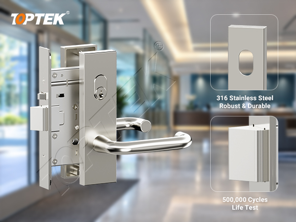
| Lock-side information | What the strike enquiry must resolve |
|---|---|
| TKAU6400 main latch projection: 15 mm. | Keeper capacity, engagement and release clearance with the actual door gap. |
| Auxiliary deadlatch projection: 8.5 mm. | Its contact position when the door is closed, relative to the moving keeper. |
| Selected mechanical lever function and handing. | Outside access, inside operation and the path of the latch during opening. |
| Door and frame section. | Strike body space, fixing support and permitted preparation. |
Use these dimensions with the TKAU6400EC product configuration. For other models in the Australian mortice lock range, obtain their own drawings instead of carrying this interface across the entire range.
Specify the release sequence in plain language
An electric strike controls a frame-side keeper; it does not turn a locked mechanical lever into an unlocked lever. A useful enquiry therefore states what an authorised user should do after presenting a credential and what a person inside should do to leave.
For example, describe whether the outside user pulls or pushes the door after the keeper releases, and whether any handle action is expected. Confirm this against the selected lock function and furniture. The integrator can then choose the strike’s power-loss behaviour and controls without confusing those settings with the mechanical lock’s operation.
The Lockwood ES200 specification illustrates why an exact strike reference matters: it separates voltage variants and selectable fail-safe/fail-secure operation. It is a strike-selection reference, not a statement that ES200 is compatible with TKAU6400.
Check release on the opening, not only on the bench
The assembled sample needs the proposed lock, strike, frame preparation and control setting. Confirm that it latches on closing, releases on the authorised command and relatches after the user passes through. Check the auxiliary contact and the expected handle operation from each side.
A door that releases freely while unloaded may behave differently when seals or a user pulling the door apply force to the keeper. Ask the strike supplier about its permitted preload conditions; a holding-force rating does not by itself specify release under load. If the mechanical latch is already binding without the strike involved, use the latch retraction checks to identify that separate problem.
For a fire-resisting doorset, obtain approval for the proposed hardware and frame preparation within the applicable doorset evidence. Approval of either component alone is not approval of every combination.
Request a lock-side compatibility review
Send the TKAU6400 configuration, proposed strike model, its drawing, a door/frame section and the required access sequence. These inputs let TOPTEK’s commercial hardware team address the lock interface while the strike supplier confirms its own application limits. Request the TKAU6400 drawing for your proposed strike combination.
Frequently Asked Questions
Does a 15 mm latch projection mean a 15 mm-deep strike is suitable?
No. Keeper geometry, engagement, door gap, release clearance and auxiliary deadlatch contact must be checked together for the proposed combination.
Does choosing fail-safe on the strike define the whole door’s exit function?
No. That setting describes the strike’s response to power loss. Inside and outside operation also depend on the mechanical lock function, furniture and complete project arrangement.