

Lift-Lever Multipoint Lock Mechanism Explained: Operation, Selection and Installation Risks
A lift lever multipoint lock mechanism asks the user to raise the handle so that the central gearbox moves the remote hooks or deadbolts into their keeps. In a common sequence, the cylinder is then turned to provide secondary deadlocking and prevent the handle from retracting the points. Reliable operation depends on the lock, lever, spindle, cylinder, long faceplate, keeps, door alignment and seals working as one system.
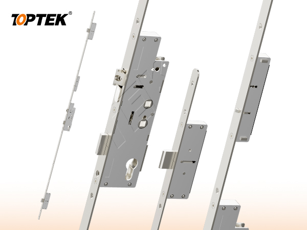
This guide explains the operating states and the checks a door manufacturer should control before approving production. Buyers can first review the TOPTEK multi-point locking systems range, then match the exact function to a controlled door and frame drawing.
TL;DR
A lift-lever multipoint lock uses upward handle movement to project its locking points; a separate cylinder action may then deadlock the mechanism.
- Do not confuse lift-to-lock operation with automatic projection or cylinder-driven projection.
- The lever set must support upward travel, the required torque and correct return behavior—not only normal downward latch operation.
- Spindle engagement, cylinder cam logic, hook/keep alignment, seal compression and long-faceplate straightness must be approved together.
- Test the mechanism on a production-representative door under agreed alignment and gasket conditions.
- Define user instructions clearly: closing the door alone may leave the remote points retracted.
Quick Answer: How Does a Lift-Lever Multipoint Lock Work?
After the door closes, the user raises the lever; the spindle rotates the follower and gearbox, which drives the connecting mechanism and projects hooks or deadbolts at several positions. Where the design includes secondary cylinder locking, turning the key or thumbturn then deadlocks the projected state and prevents normal handle retraction. Unlocking reverses the cylinder state, after which pressing the lever down retracts the points and latch as designed. The exact sequence must be confirmed for the selected model.
Key Takeaways for Door and Hardware Buyers
The selection decision is not only “lift lever or not”; it is a complete compatibility decision covering the user’s action, force path, door geometry and evidence route.
- Approve a written state sequence before freezing machining or lever furniture.
- Confirm that the lever mechanism is designed for upward as well as downward travel.
- Treat the spindle, follower and cylinder cam as functional components, not generic accessories.
- Validate every remote point against its keep with real seals and realistic door alignment.
- Separate manufacturer validation from independent certification and complete-door approval.
What Is a Lift Lever Multipoint Lock Mechanism?
It is a manually actuated multipoint system in which upward lever rotation supplies the movement needed to project remote locking points. The central case transfers handle movement through internal gears, sliders or linkages to hooks, deadbolts or other points positioned along the door edge.
The mechanism is different from an automatic multipoint lock, which releases its points through a closing trigger, and from a cylinder-driven system, in which key rotation supplies the primary projection movement. This distinction affects user training, accessibility, hardware selection and the way the door must be tested.
Early engineering CTA: Send the door profile, intended handle sequence, spindle and cylinder requirement to ivan.he@toptekaccess.com before door machining or tooling is frozen.
Lift-Lever Multipoint Lock Operating Sequence
A usable approval document should describe what the user does, what moves and what state the door reaches at each step. The sequence below represents a common lift-to-lock arrangement; the selected product’s controlled instructions remain authoritative.
1. Close the door and engage the latch
The door reaches the frame and the latch enters its strike. At this stage, the remote hooks or deadbolts may still be retracted. Closing alone should not be described as full multipoint locking unless the exact product is also automatic.
2. Raise the lever handle
The user rotates the lever upward through its designed travel. The lever, spring cassette or bearing structure, spindle and lock follower must transmit this movement without bottoming, slipping or excessive deformation.
3. Transfer movement through the central case
Follower movement drives the central gearbox or slider. That movement is transmitted along the lock edge to the remote points. Friction, tolerance accumulation and faceplate distortion can change the effort felt at the handle.
4. Project hooks or deadbolts into their keeps
Each point must meet an aligned frame keep. If one hook contacts the edge of its keep, the user may be forced to lift harder even though the central lock case is correctly assembled.
5. Apply secondary cylinder deadlocking where specified
In a common TOPTEK-described lift-lever arrangement, turning the cylinder after lifting the handle provides a second locking stage and prevents the handle from being pressed down to open. Because designs vary, buyers must verify cylinder turns, key withdrawal, thumbturn behavior and escape requirements for the exact model.
6. Unlock, press down and reset
The cylinder is returned to the release state where applicable. Pressing the handle down then retracts the remote points and performs the specified latch operation. The mechanism must return fully so the next cycle begins from a known state.
Lift-Lever Lock State Matrix
This state matrix helps specification teams distinguish “door closed,” “points projected” and “points deadlocked” instead of treating them as one condition.
| Observed state | User action | Remote points | Handle behavior | Approval question |
|---|---|---|---|---|
| Door closed, handle not lifted | Close only | Normally retracted in a pure lift-lever sequence | Available for lifting | What security state exists before the user lifts? |
| Points projected | Lift handle | Hooks/deadbolts enter keeps | Returns as designed | Can points retract by pressing down before cylinder deadlocking? |
| Secondary deadlocked | Turn cylinder after lifting | Remain projected | Retraction is blocked as designed | Which inside/outside actions remain permitted? |
| Unlocked and reset | Release cylinder, then press handle | Retract | Returns to starting position | Does the complete sequence reset consistently? |
Lift-Lever vs Automatic vs Cylinder-Driven Multipoint Locks
The architectures are defined by the action that projects the points, and that action changes both the user experience and the integration risk.
| Architecture | Projection action | User-dependent step | Primary project risk |
|---|---|---|---|
| Lift-lever | Raise handle | User must lift before any secondary deadlocking | Wrong lever/spindle, high effort or incomplete lift |
| Automatic | Closing trigger releases points | User may still need a separate deadlocking action | Trigger timing and premature or missing release |
| Cylinder-driven | Key or cylinder drives points | User must turn the cylinder | Excessive key/cylinder load or incomplete rotation |
Selection Checklist for a Lift Lever Multipoint Lock
The correct mechanism must match the required user sequence, door construction and full hardware set—not only the nominal lock dimensions.
| Control point | Buyer input | What to approve |
|---|---|---|
| User operation | Who uses the door and what actions are acceptable | Written inside/outside sequence and instructions |
| Lever handle | Upward/downward travel, return, fixing and duty | Complete lever-lock sample under realistic load |
| Spindle and follower | Section, length, engagement and door thickness | No bottoming, slipping or insufficient engagement |
| Cylinder | Profile, cam, length, turns and thumbturn/key logic | Secondary deadlocking and release state |
| Lock geometry | Backset, centres, faceplate and case envelope | Model-specific controlled drawing |
| Remote points and keeps | Type, direction, positions and engagement | Common-datum door/frame coordinate drawing |
| Door and seals | Material, profile, gasket pressure, hinges and closer | Representative installed-door sequence |
| Evidence route | Market, product standard and doorset requirement | Exact model, report scope and project approval |
Why the Lever Handle and Spindle Must Be Approved with the Lock
A normal downward-operating lever is not automatically suitable for a lift-to-lock mechanism. The handle structure must permit upward rotation, carry the required operating load, return correctly and keep stable spindle engagement through repeated use.
Review lift angle and available travel, spring or bearing behavior, through-bolt positions, rose or backplate clearance, door thickness, spindle section and length, fixing torque and collision with the frame. The TOPTEK EN 1906 lever-handle range provides product starting points, but upward-operation compatibility must still be confirmed for the selected lock and lever combination.
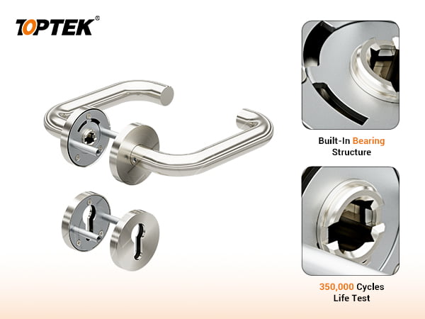
A spindle that is too short may not engage reliably. A spindle that is too long may bottom out or preload the furniture. Over-tightened roses or misaligned through-bolts can add friction at the follower. These interfaces should be inspected before blaming the lock gearbox.
Installation Risks That Change Lift-Lever Operation
Installation can change handle effort and point travel even when every individual component passed an incoming check.
Risk 1: Keep misalignment across the door height
A hook that rubs one keep can increase force throughout the linkage. Reference all keeps from common datums and verify engagement at every point.
Risk 2: Door sag or gasket compression
Hinge movement and seal pressure change the position and preload of the leaf. Test the lift action with the actual gasket and agreed alignment limits.
Risk 3: Wrong spindle length or lever structure
Insufficient engagement, bottoming, a downward-only return cassette or poor fixing alignment can prevent full lift travel.
Risk 4: Cylinder cam or sequence conflict
The wrong cylinder format, length, cam or rotational logic can block secondary locking or prevent release. Test every permitted key and thumbturn state.
Risk 5: Long faceplate distortion
TOPTEK’s project experience shows that multipoint faceplates commonly exceed 1.7 metres. Bending during installation or shipment can add friction and change the force path.
Risk 6: Debris and unsuitable friction pairs
Machining debris can obstruct the central case or linkage. TOPTEK has also reviewed designs in which zinc alloy rubbed directly against steel, creating an avoidable wear risk. Review contact material, load, lubrication and wear path.
Common Selection Mistakes
The most expensive mistakes are usually decisions made before a complete state sequence or door-mounted sample exists.
- Assuming the user will know to lift: product instructions, signage or application design may need to address the manual step.
- Choosing the handle by appearance: upward travel and load transfer are functional requirements.
- Approving backset and centres only: spindle, follower, cylinder, faceplate, points, keeps and door preparation also control compatibility.
- Testing with the door open only: the frame and seals create the operating load that matters.
- Using installer adjustment as the acceptance method: define measurable drawing and function criteria for production.
- Equating internal testing with certification: keep manufacturer validation and third-party evidence separate.
Sample Approval and Production Validation
A production-representative door-mounted sample should prove the operating states and become the controlled reference for mass production.
- Freeze the function statement, handing, user actions and permitted inside/outside states.
- Approve the lever, spindle, cylinder, lock, keeps, fasteners and door preparation as one bill of materials.
- Operate the mechanism with the door open to confirm basic travel without frame load.
- Operate it with the door closed using the intended gaskets, hinges and closer.
- Record an agreed method for lift effort, full point projection, cylinder deadlocking, release and reset. Do not invent a universal force limit.
- Test approved alignment and seal-pressure boundary conditions.
- Convert critical dimensions and state checks into incoming, in-process and final inspection records.
- Protect long assemblies individually and control faceplate straightness after transport.
EN 15685, EN 1906 and Evidence Boundaries
Product standards and test reports help define evidence, but they do not remove the need to approve the exact lever-lock-door configuration. BSI lists BS EN 15685:2024 for multipoint locks, latches and locking plates. BSI also publishes an EN 1906 lever-furniture reference. Buyers should check the current edition, national adoption, classification and exact model scope at approval.
TOPTEK uses EN 15685 as an engineering and internal-test reference where applicable and evaluates prototypes and tooling samples in its own laboratory before bulk production. That is manufacturer validation, not automatic third-party certification. If the project needs independent testing or a fire-rated door route, confirm the applicable scope with an organization such as Intertek Building & Construction or the relevant UL Solutions door and hardware guidance. A report for one lever, lock or doorset does not automatically cover a different multipoint configuration.
Use the TOPTEK certification resource centre to locate published documents, then verify the model, revision, issuing body, installation conditions and authorized claim against the project specification.
Project Risk Summary
The main risks are incomplete user operation, incompatible lever/spindle geometry, excessive linkage load, misaligned keeps, cylinder-sequence errors, faceplate deformation and overstated evidence.
These risks can create a door that appears closed but has no remote points engaged, a handle that cannot complete its lift, a cylinder that cannot deadlock or release, or a batch that requires repeated site adjustment. For deeper troubleshooting context without changing this article’s selection intent, use TOPTEK’s guide on why multipoint locks become hard to operate.
TOPTEK Evidence and Engineering Information Gain
TOPTEK combines more than five years of direct multipoint-lock production and development experience with a lock-manufacturing base established in 1991. The engineering workflow includes drawing review, prototype and tooling-sample validation, internal laboratory checks and controlled mass-production release.
For multipoint projects, the team reviews automatic, lift-lever and cylinder-driven logic; steel hook and deadbolt combinations; lever/spindle/cylinder interfaces; long-faceplate protection; and door-mounted operation. Individually protected wooden-case packing is used for long multipoint assemblies to reduce transport deformation risk.
TOPTEK’s broader manufacturing resources include a 13,000 m² facility, a 20+ person R&D team, precision machining and stamping capability, and ISO 9001, ISO 14001 and ISO 45001 management systems. These capabilities support repeatability; project approval still depends on the exact product and evidence route.
Product Scope and Selection Boundary
TOPTEK’s multipoint portfolio includes PD1000, Auto Lock and EU001 platform discussions, but buyers must map each platform to its verified operating sequence. A photograph or family name is not a substitute for the model drawing, function statement and sample. Automatic and lift-lever terminology must not be interchanged.
Lift-Lever Multipoint Lock RFQ Checklist
A qualified RFQ should describe the operating sequence and every mechanical interface that can affect upward handle movement.
- Door material, profile section, thickness, height, width and intended application.
- Opening direction, handing and inward/outward operation.
- Required close, lift, secondary deadlock, unlock, retract and reset sequence.
- Inside/outside access, key, thumbturn, emergency or escape requirements.
- Backset, handle/cylinder centres, case envelope and faceplate dimensions.
- Lever model, upward/downward travel, return mechanism and fixing pattern.
- Spindle section, length, split/solid format and effective engagement.
- Cylinder profile, length, cam, number of turns and key-withdrawal state.
- Remote point types, coordinates, keeps and expected engagement.
- Gasket, hinge, closer, alignment tolerance and site-adjustment plan.
- Target market, applicable standard, report or doorset evidence requirement.
- Forecast quantity, finish, sample stages, inspection, packaging and delivery route.
Why TOPTEK for Lift-Lever Multipoint Projects?
TOPTEK can review the force path and interfaces that connect the user’s hand movement to every remote locking point. The team supports OEM/ODM drawing review, function definition, sample planning, material and friction-pair review, internal validation, production control and export packaging.
The objective is to approve a mechanism that works on the intended door and to convert that approved state sequence into repeatable production checks.
Frequently Asked Questions
These answers cover the main operation and approval questions for a lift lever multipoint lock mechanism.
What is a lift lever multipoint lock mechanism?
A lift lever multipoint lock mechanism uses upward handle movement to drive a central case and project hooks, deadbolts or other locking points along the door edge.
Does closing the door fully lock a lift-lever multipoint system?
Not usually in a pure lift-lever sequence. The user must raise the handle to project the remote points, and the exact design may then require a cylinder action for secondary deadlocking.
Why is the cylinder turned after lifting the handle?
In a common secondary-locking sequence, cylinder rotation deadlocks the projected state and prevents normal handle retraction. Confirm the exact behavior for the selected model.
Can any lever handle operate a lift-lever multipoint lock?
No. The lever must support the required upward travel, operating load, return behavior, fixing pattern and spindle interface for the selected lock.
What should be tested on the installed door?
Test closing, upward lift, full point projection, cylinder deadlocking, release, downward retraction and reset with the intended keeps, gaskets, hinges, closer and alignment conditions.
Does internal testing prove third-party certification?
No. Internal testing supports manufacturer development and quality control; third-party certification or doorset approval must be verified through the exact model, report, scope and project route.
Conclusion: Approve the Complete Lift-to-Lock State Sequence
A lift lever multipoint lock mechanism should be selected and tested as a complete force path: lever, spindle, follower, central case, linkage, remote points, keeps, cylinder and door. Approving only the lock body or nominal dimensions leaves user, installation and production risks unresolved.
Primary CTA: Send your door profile, required operating sequence, lever/spindle/cylinder details, target market, evidence route and forecast quantity to ivan.he@toptekaccess.com for drawing or RFQ review.
Secondary CTA: Use the TOPTEK contact page to submit controlled drawings and request a sample-validation discussion.
TOPTEK stands for Commercial Door Hardware Reliability Solution. TOPTEK: Smart Design. Strong Security.
Product scope: ANSI Grade 1 mortise locks, EN 12209 Grade 3 mortise locks, AS 4145 mortise locks, multipoint locks, cylinders, EN 1906 lever handles, panic exit devices, electronic locks, hinges, door closers and related OEM/ODM commercial door hardware.