

Access Control Door Hardware Guide: Lock, Power, Controller and Door Interfaces
TL;DR
Access control door hardware must be scheduled as a system: credential reader, controller and relay logic, power supply, electronic lock, door power transfer, inside egress, monitoring contacts, mechanical override, door position and closer. Start with the required operating states, then select model-specific electrical and physical interfaces. Never infer voltage, current or fail state from a product-family name.
Start with the Electronic Lock and Access Control product hub, then use this narrower guide to define the required function and approval evidence.
Quick Answer
Create one state table for normal power, authorised entry, locked condition, inside egress, mechanical override, alarm input where applicable, and power loss. Assign a responsible party to every signal and component. Bench-test the identified configuration, then commission it on the actual door.
Map the complete signal path
A credential at the reader becomes a controller decision, a relay or data output, and then a change at the lock. The opening may also return door-position, latch-state, request-to-exit or other model-specific signals. Draw this path before selecting part numbers so the integrator and hardware supplier agree on boundaries.
Do not use “compatible with access control” as a complete specification. Identify the controller output type, power source, lock input, cable conductors, monitoring contacts and required timing. If an interface is not confirmed in the current model documentation, keep it open in the RFQ.
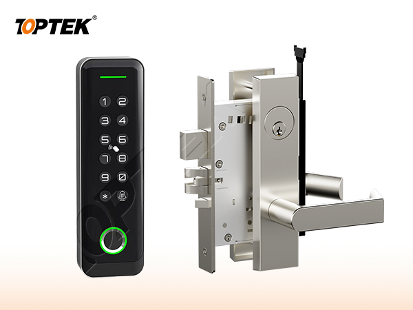
Define power and power-loss behaviour
Voltage is only one electrical field. The design must also confirm current demand, inrush where relevant, duty, polarity requirements, cable length and voltage drop, power-supply capacity and backup strategy. TOPTEK internal material describes 12–24 V flexibility for certain solenoid families, but that statement must be confirmed per quoted model.
Fail-safe and fail-secure describe the intended power-loss state of a controlled function; they do not by themselves approve egress, fire response or overall building security. The responsible designer determines the required state. The supplier provides the exact configuration data and evidence.
Coordinate the electronic mortise lock function
TOPTEK’s source differentiates solenoid-controlled and motorized mortise-lock families, and it identifies EN solenoid self-locking variants. The actuator type does not fully define the opening. The schedule must still state what the outside lever, inside lever, latch, deadbolt and cylinder do in every state.
C-designations in the supplied model list indicate a cross-latch-bolt variant, while non-C models use the ordinary latch form described in the source. Treat that as a family coding note to confirm on the current quotation and drawing, not a universal rule beyond the listed range.
Plan power transfer and cable protection
The moving door needs a suitable path from frame wiring to the lock. Depending on the approved design, this may use a door loop, electric hinge or concealed power-transfer device. Coordinate conductor count and gauge, connector locations, bending, door swing, hinge reinforcement and service access.
A correct lock can fail if the cable is pinched, too short, repeatedly flexed outside its design or routed through an unapproved opening. Keep the power-transfer device on the same door elevation and wiring schedule. Assign installation and continuity testing responsibility.
| Interface | Define | Verify |
|---|---|---|
| Controller to lock | Output/relay logic and timing | Command produces approved lock state |
| Power supply | Voltage, current, capacity, backup | Loaded voltage at the door |
| Door transfer | Conductors, gauge, movement, connectors | Continuity through full swing |
| Lock and trim | Lever, latch/deadbolt, cylinder, hand | Every normal and override state |
| Monitoring | Contact type and controller meaning | Displayed state matches physical state |
| Power loss/alarm | Responsible system and required response | Documented witnessed test |
Keep egress, override and monitoring independent
Inside egress must be defined for normal power and power loss, while mechanical override provides a separate authorised access path. Monitoring reports states; it should not be assumed to create the release function. Write each requirement separately so one feature is not mistaken for another.
TOPTEK’s electronic mortise-lock source describes inside escape operation and outside access through an access-control terminal for certain families. Confirm the exact inside trim, cylinder override and contact set on the quoted model. System designers remain responsible for the approved life-safety sequence.
Approve the opening as a system
Electronic Lock and Access Control is only one part of the opening. The door leaf, frame, strike or rod interfaces, trim, cylinder, closer, power components where applicable, and the installation conditions all influence the result. Review the TKAMSEC9200(EC) solenoid page, the TKAMMRR9200(RR) motorized page and the electronic product hub as configuration starting points. A catalogue family name cannot replace a coordinated opening schedule.
Give every opening a unique number. Attach the current elevation, door and frame construction, thickness, swing, handing, hardware interfaces, finish, evidence requirements and sample reference. When one field changes, reopen the affected checks instead of assuming that the earlier approval remains equivalent.
Use a state-based approval test
Write the normal, locked, authorised-entry, emergency-egress, override and abnormal states that apply. For each state, record what the user does and what each latch, bolt, rod, lever, key or electrical input must do. Mark a state N/A when it truly does not apply; a blank field hides a decision.
Operate the labelled sample in the same sequence. Review from both sides of the door, then repeat the critical checks in representative preparation. Photograph labels and interfaces, but preserve the signed state table as the controlling approval record. Appearance alone cannot prove function.
Separate product evidence from project approval
A certificate, test report or declaration applies only to the product, construction, standard and configuration named in its scope. A project still needs to determine whether that evidence is the document it requires. Request current original records and compare model identifiers with the quotation, drawing and sample.
Do not turn an internal development test, a website badge, a similar model or a customer statement into third-party certification. If evidence remains open, record the missing document, responsible reviewer and due date. This draft intentionally avoids unsupported cycle, load, corrosion, fire or material claims.
Buyer approval checklist
- Opening number, door type, frame and swing
- Plain-language operating sequence from both sides
- Exact product, trim and interface references
- Door preparation and installation tolerances
- Required model-specific evidence and revision
- Labelled sample and acceptance owner
- Packaging, site inspection and handover controls
- Repeat-order change-control reference
Common mistakes and project risks
Typical errors are specifying only the reader, copying voltage from another model, confusing monitored status with control logic, omitting voltage-drop calculation, forgetting the door power-transfer path, and approving normal entry without testing egress, power loss and override. Another risk is letting the hardware schedule and access-control drawings use different opening numbers.
The practical consequences can include re-machining, replacement hardware, revised wiring or keying, delayed inspection and uncontrolled site modification. Stop approval when the operating sequence, physical interface or evidence scope is unclear. A question recorded before production costs less than an assumption discovered across installed doors.
TOPTEK evidence and product scope
TOPTEK uses product-family material, model images and internal engineering observations to frame the buyer questions in this guide. These sources support a configuration discussion; they do not make every option, dimension or approval universal. The supplied configuration still has to be identified on a current drawing.
Use the TOPTEK resources centre for product documents and the applicable evidence request. Where a source describes internal testing, treat it as internal verification unless an original third-party document for the quoted configuration is separately reviewed.
RFQ checklist
- Opening state table and control narrative
- Exact lock model, actuator and fail-state configuration
- Voltage, current, duty, polarity and cable-distance data
- Controller/relay and monitoring contact requirements
- Reader, REX, door position, override and egress interfaces
- Door loop, electric hinge or power-transfer specification
- Required evidence list and market/project basis
- Sample quantity, acceptance tests and owner
- Drawing, quotation and order revision control
- Production labels and packaging requirement
Why TOPTEK: turn selection into a controlled record
TOPTEK can review a marked-up schedule, translate shorthand into operating and interface questions, and identify missing information before quotation. The objective is not to guess the designer’s decision; it is to give the responsible parties a clear configuration to approve.
Quotation, drawing, sample label and order acknowledgement should carry the same reference. This lets door manufacturers, distributors, integrators and project teams detect substitutions or later changes. It also creates a practical basis for repeat-order inspection.
Two-level CTA
For an initial review, send the opening list, door images or elevations and the required user sequence. Highlight unknowns. TOPTEK can return a focused question list without presenting assumptions as confirmed facts.
For a formal RFQ, submit the approved schedule, drawings, interfaces, evidence requirements and sample protocol through the TOPTEK contact page. Request a configuration-specific response and identify the person authorised to approve deviations.
Conclusion
Good hardware selection is a controlled translation from user behaviour to product configuration. Define the function, verify the physical interfaces, check the applicable evidence and demonstrate the identified sample. Do not let a general product name carry decisions it cannot contain.
Preserve the result through procurement, production, installation and handover. That discipline reduces avoidable replacement risk while keeping every TOPTEK statement inside the evidence and configuration actually reviewed.
Frequently asked questions
What is included in access control door hardware?
It can include the electronic lock, reader, controller interface, power supply, cable transfer, request-to-exit, monitoring, cylinder override, trim, closer and door-position components.
Can voltage be selected from the product-family name?
No. Confirm voltage, current, duty, polarity and wiring data for the exact quoted model and system.
Does fail-secure mean the door cannot be exited during power loss?
Not necessarily. Fail state and inside egress are separate requirements; define and test both on the approved configuration.
Why is door power transfer part of the lock RFQ?
It determines how conductors reach the moving door and must match conductor count, door movement, reinforcement and service needs.
What should be tested before production approval?
Test authorised entry, locked state, inside egress, power loss, mechanical override, monitoring and every applicable alarm or release input.